The information that is displayed on the mnemonic diagram can be presented in the form of an analog, discrete and relay signal, as well as graphically. Visually displaying the structure of the system, the mnemonic diagram makes it easier for the operator to memorize the schemes of objects, the relationship between parameters, the purpose of devices and controls. In the control process, the mnemonic diagram is the most important source of information for the operator about the current state of the system, the nature and structure of the processes occurring in it, including those associated with a violation technological modes, accidents, etc.
The mnemonic diagrams reflect the main equipment, signals, the state of the regulatory bodies. Mnemonic diagrams can reflect both the general picture of the state of the system, the technological process, and the state of individual units, devices, parameter values, etc. Auxiliary and reference material should be located in additional display forms, with the ability to extract these auxiliary forms to the screen as quickly as possible.
Mnemonic schemes help the operator, working in conditions of a large amount of incoming information, to facilitate the process of information retrieval, subordinating it to a certain logic dictated by the real connections of the parameters of the controlled object. They facilitate the operator's logical systematization and processing of incoming information, help to carry out technical diagnostics in case of process deviations from the norm, provide an external support for developing optimal solutions and forming control actions.
Mnemonic diagrams are effectively used in cases where
- managed object has a complex technological scheme and a large number of controlled parameters;
- the technological scheme of the object can be quickly changed in the process of work.
Mnemonic diagrams are based on several basic principles
- the principle of conciseness, according to which the mnemonic diagram should be simple, should not contain unnecessary, obscuring elements, and the displayed information should be clear, specific and concise, convenient for perception and further processing.
- the principle of generalization and unification provides for the requirement according to which it is necessary to single out and use the most significant features of managed objects, that is, elements denoting insignificant elements should not be used on the mnemonic diagram design features systems, and the symbols of similar objects and processes should, if possible, be combined and unified.
- the principle of emphasis - to the elements of control and management on mnemonic diagrams, first of all, it is necessary to highlight the size, shape or color of the elements that are most essential for assessing the state, making decisions and influencing the controlled object.
- the principle of autonomy provides for the need to isolate from each other sections of the mnemonic diagram corresponding to autonomously controlled and managed objects and units. These isolated areas should be clearly demarcated from others and, according to the principle of structure, should have a complete, easy to remember and different structure. The structure should reflect the nature of the object and its basic properties.
- the principle of spatial correlation of control and management elements, the location of instrumentation and indicator devices must be clearly coordinated with the location of the corresponding control elements, that is, the law of compatibility of stimulus and reaction must be observed.
- the principle of using habitual associations and stereotypes involves the use on mnemonic diagrams of such conditional designations of parameters that are associated with the generally accepted letter designations of these parameters. It is desirable to use, if possible, instead of abstract signs, symbols associated with objects and processes.
The main task of the mnemonic diagram
Displaying the logic of controlled and managed processes, to help simplify the search and identification of the necessary information and promptly make the right decisions.
Classification of mnemonic diagrams by type
Operator
Display, as a rule, a single spatially concentrated technological complex Depending on whether the operator performs any switching directly on the mnemonic diagram or it is a purely informational information device, operator mnemonic diagrams are divided into operational and non-operational
- operational mimics along with various devices displays, devices, visual and signal elements have controls of an individual or calling type.
- non-operational
Control rooms
They display a dispersed system, which includes a variety of technological complexes, objects, units. Depending on whether the operator performs any switching directly on the mnemonic diagram or it is a purely informational information device, control rooms are divided into light and mimic
- light
- mimic - manual switches for removing signals and bringing the display of the state of the object on the mnemonic diagram in accordance with its real state.
Operator and dispatcher mnemonic diagrams differ significantly in the degree of detail and display detail of individual control and management objects.
Individual
Individual or single-object mnemonic diagrams - mnemonic diagrams in which each information element is associated with only one sensor, that is, circuit sections are constantly connected to the same controlled objects.
calling
Calling mnemonic circuits or selective (multi-object) - mnemonic circuits in which sections can periodically or as necessary be connected to several objects that have the same structure, are called calling or selective (multi-object). In calling mnemonics, either one or another object, or one or another sensor of one object can be connected. With the help of a calling mnemonic circuit, it is possible to significantly reduce the size of the panel, save in instruments and SDI, and facilitate the operator's working conditions by reducing the field of view and simplifying the circuit.
Permanent
A permanent mnemonic is a mnemonic that constantly displays the same object diagram. In replaceable mnemonic circuits, the image during operation can change significantly depending on the operating modes of the object (starting circuit, normal operation circuit, emergency circuit, etc.).
Classification of mnemonic diagrams by type
Location
- individual panels
- add-on to the instrument panel
- attachment to the console
- operating panel of the remote control
Information on the mimic
- analog
- analog-discrete
- discrete
Symbols of the object, unit, production line and other equipment
- flat
- embossed
- voluminous
Encoding method
- conditional
- symbolic
Symbols on mnemonic diagrams
Conventional signs do not have any external resemblance and do not create visual associations with displayed objects and phenomena.
When developing mnemonic diagrams, it is important optimal choice forms of symbols used. The shape of the symbols should be a closed loop. Auxiliary elements and lines should not cross the outline of the character or in any other way make it difficult to read.
Increased requirements should be imposed on symbols that signal the functional (special emergency) state of individual units or objects.
Connecting lines on the mimic
Must be straight and solid. When laying out the mnemonic diagram, it is necessary to strive for connecting lines to be as short as possible and have the least number of intersections.
Specifics of working with mnemonic diagrams
When working with mnemonic diagrams of considerable size and many objects of different colors and brightness, the operator's visual system is subjected to a heavy load. Therefore, it is not allowed to use a large number of colors that quickly tire the eyes - red, purple, purple. It is recommended to use low-saturated colors of the middle frequency of the spectrum as the background of mnemonic diagrams.
Evaluation of mnemonics
Occurs in two ways
- The information content coefficient is the ratio of the number of passive elements and active ones.
- The field filling factor is the ratio of the number of passive elements of mnemonic diagrams to the total number of elements of the mnemonic diagram.
Write a review on the article "Mnemonic"
Links
An excerpt characterizing the Mnemonic diagram
The Emperor ducked his ear, frowning slightly to show that he hadn't heard.“I’m waiting, your Majesty,” Kutuzov repeated (Prince Andrey noticed that Kutuzov’s upper lip, while he was talking this I'm waiting). “Not all the columns have gathered yet, Your Majesty.
The sovereign heard, but this answer, apparently, did not please him; he shrugged his stooped shoulders, glanced at Novosiltsev, who was standing beside him, as if complaining about Kutuzov with this look.
“After all, we are not in the Tsaritsyn Meadow, Mikhail Larionovich, where they don’t start the parade until all the regiments arrive,” said the sovereign, again looking into the eyes of Emperor Franz, as if inviting him, if not to take part, then listen to what he He speaks; but Emperor Franz, continuing to look around, did not listen.
“That’s why I don’t start, sir,” said Kutuzov in a sonorous voice, as if warning the possibility of not being heard, and something trembled in his face again. “That’s why I don’t start, sir, because we are not at the parade and not on the Tsaritsy’s Meadow,” he said clearly and distinctly.
In the retinue of the sovereign, all the faces, instantly exchanging glances with each other, expressed murmuring and reproach. "No matter how old he is, he shouldn't, he shouldn't speak like that," these faces expressed.
The sovereign looked intently and attentively into Kutuzov's eyes, waiting for him to say something else. But Kutuzov, for his part, bowing his head respectfully, also seemed to be waiting. The silence lasted for about a minute.
“However, if you order, your Majesty,” said Kutuzov, raising his head and again changing his tone to the former tone of a stupid, unreasoning, but obedient general.
He touched the horse and, having called the head of the column Miloradovich to him, gave him the order to advance.
The army stirred again, and two battalions of the Novgorod regiment and a battalion of the Apsheron regiment moved forward past the sovereign.
While this Apsheron battalion, ruddy-faced Miloradovich, without an overcoat, in a uniform and orders and with a hat with a huge sultan, put on sideways and from the field, was passing, the march galloped forward and, valiantly saluting, reined in the horse in front of the sovereign.
“God bless you, general,” the emperor told him.
- Ma foi, sire, nous ferons ce que qui sera dans notre possibilite, sire, [Really, your majesty, we will do what it will be possible for us to do, your majesty,] - he answered cheerfully, nevertheless causing a mocking smile from the gentlemen retinue of the sovereign with his bad French accent.
Miloradovich abruptly turned his horse and stood somewhat behind the sovereign. The Absheronians, excited by the presence of the sovereign, valiantly, briskly beating off their feet, passed by the emperors and their retinues.
- Guys! - Miloradovich shouted in a loud, self-confident and cheerful voice, apparently excited to such an extent by the sounds of shooting, the expectation of battle and the sight of the fine fellows of the Apsheron, still their Suvorov comrades, briskly passing by the emperors, that he forgot about the presence of the sovereign. - Guys, you do not take the first village! he shouted.
- Glad to try! the soldiers shouted.
The sovereign's horse shied away from an unexpected cry. This horse, which had carried the sovereign at reviews in Russia, here, on the Field of Austerlitz, carried its rider, withstanding his scattered blows with his left foot, alerted his ears to the sounds of shots, just as she did it on the Field of Mars, not understanding the meaning of any these heard shots, nor the neighborhood of the black stallion of Emperor Franz, nor everything that the one who rode it said, thought, felt that day.
The sovereign turned to one of his entourage with a smile, pointing to the fellow Absherons, and said something to him.
Kutuzov, accompanied by his adjutants, rode at a pace behind the carabinieri.
Having traveled half a verst at the tail of the column, he stopped at a lonely abandoned house (probably a former tavern) near the fork of two roads. Both roads descended downhill, and troops marched along both.
The fog began to disperse, and indefinitely, at a distance of two versts, enemy troops could already be seen on opposite hills. To the left below the shooting became more audible. Kutuzov stopped talking to the Austrian general. Prince Andrei, standing somewhat behind, peered at them and, wanting to ask the adjutant for a telescope, turned to him.
“Look, look,” this adjutant said, looking not at distant army and down the mountain in front of you. - They're French!
Two generals and adjutants began to grab the pipe, pulling it out one from the other. All the faces suddenly changed, and horror was expressed on everyone. The French were supposed to be two miles away from us, but they appeared suddenly, unexpectedly in front of us.
- Is this an enemy? ... No! ... Yes, look, he ... probably ... What is this? voices were heard.
Prince Andrey with a simple eye saw a dense column of Frenchmen rising to the right towards the Apsheronians, no further than five hundred paces from the place where Kutuzov was standing.
“Here it is, the decisive moment has come! It came to me, ”thought Prince Andrei, and hitting his horse, drove up to Kutuzov. “We must stop the Apsheronians,” he shouted, “your excellency!” But at the same moment, everything was covered in smoke, close-range shooting was heard, and a naively frightened voice, two steps away from Prince Andrei, shouted: “Well, brothers, the Sabbath!” And as if this voice was a command. At this voice, everything rushed to run.
Mixed, ever-increasing crowds fled back to the place where five minutes ago the troops passed by the emperors. It was not only difficult to stop this crowd, but it was impossible not to move back together with the crowd.
Bolkonsky only tried to keep up with her and looked around, perplexed and unable to understand what was happening in front of him. Nesvitsky, with an angry look, red and not like himself, shouted to Kutuzov that if he did not leave now, he would probably be taken prisoner. Kutuzov stood in the same place and, without answering, took out his handkerchief. Blood was flowing from his cheek. Prince Andrei pushed his way up to him.
- Are you injured? he asked, barely able to control the trembling of his lower jaw.
- The wounds are not here, but where! - said Kutuzov, pressing a handkerchief to his wounded cheek and pointing to the fugitives. - Stop them! he shouted, and at the same time, probably convinced that it was impossible to stop them, he hit his horse and rode to the right.
The crowd of fugitives, again surging, took him with them and dragged him back.
The troops fled in such a dense crowd that, once they got into the middle of the crowd, it was difficult to get out of it. Who shouted: “Go! what's the delay?" Who immediately, turning around, fired into the air; who beat the horse on which Kutuzov himself rode. With the greatest effort, getting out of the stream of the crowd to the left, Kutuzov with a retinue, reduced by more than half, went to the sounds of nearby gun shots. Getting out of the crowd of fleeing, Prince Andrei, trying to keep up with Kutuzov, saw on the slope of the mountain, in smoke, a Russian battery still firing and the French running up to it. The Russian infantry stood higher, moving neither forward to help the battery, nor backward in the same direction as the fugitives. The general on horseback separated from this infantry and rode up to Kutuzov. Only four people remained from Kutuzov's retinue. Everyone was pale and looked at each other silently.
- Stop those bastards! - panting, said Kutuzov to the regimental commander, pointing to the fugitives; but at the same moment, as if in punishment for these words, like a swarm of birds, bullets whistled over the regiment and Kutuzov's retinue.
The French attacked the battery and, seeing Kutuzov, fired at him. With this volley, the regimental commander grabbed his leg; several soldiers fell, and the ensign, who was standing with the banner, let go of it; the banner staggered and fell, lingering on the guns of neighboring soldiers.
Soldiers without a command began to shoot.
- Oooh! Kutuzov mumbled with an expression of despair and looked around. “Bolkonsky,” he whispered in a voice trembling from the consciousness of his senile impotence. “Bolkonsky,” he whispered, pointing to the disorganized battalion and the enemy, “what is this?
But before he finished these words, Prince Andrei, feeling tears of shame and anger rising to his throat, was already jumping off his horse and running to the banner.
- Guys, go ahead! he shouted childishly.
"Here it is!" thought Prince Andrei, grabbing the staff of the banner and listening with pleasure to the whistle of bullets, obviously directed precisely against him. Several soldiers fell.
Page 15 of 20
Equipment of the Electropult plant.
Sectional mosaic control boards of the Electropult plant mainly serve to place mnemonic diagrams of electric power facilities (power plants, substations, power lines).
According to the method of reproducing information on the mnemonic diagram, the shields are made mimic and light. On the mnemonic diagrams of mimic shields, the position of individual switching devices of controlled objects ( oil circuit breakers, automata, disconnectors, etc.) is reproduced by the position of the apparatus (key) - a symbol on the shield. When a discrepancy signal is received through the telemechanics device between the actual position of the switching device and the symbol on the board, a signal lamp lights up in the latter. When the controller brings the symbol to the match position, this lamp goes out. Light boards are understood as boards, on the mnemonic diagrams of which the position of the switching devices of controlled objects is reproduced by the lighting of signal lamps various colors. As already noted, the facade field of the shield consists of removable elements 40X 40 mm in size, made of plastic.
By design removable elements are divided into two main types:
elements intended for applying on their front surfaces the symbols of tires, lines, transformers, etc., as well as elements without designations, intended to fill the free fields of the shield;
elements intended for recessed mounting of mimic or luminous symbols of equipment, keys and control buttons, signal lamp fixtures, etc.
For mounting elements of the first type on perforated boards, their design provides for two latches and two fixing protrusions made of the material of the element (Fig. 29).
In the elements of the second type (Fig. 30), there are no latches and fixing protrusions. The fastening of these elements on perforated boards is carried out with the help of mounting brackets related to the equipment to be mounted, and special rectangular washers.
The adopted method of attaching removable elements makes it possible to quick installation or replacements on switchboard panels without the use of special tools.
Rice. 29. General form and fastening of elements without built-in equipment of the mosaic shield of the Electropult plant.
To indicate on the mnemonic diagrams the operations of bringing equipment into repair, disabling protection, applying protective earth etc. on the front sides of the removable elements of the second type, holes are provided that allow hanging flags with appropriate warning signs. 
Rice. 30. Common view and fastening of elements with built-in equipment of the mosaic shield of the Electropult plant.
Mnemonic designations of sections of circuits and equipment on removable elements, with the exception of symbols of generators, switches and disconnectors, are made of 1.5 mm thick aluminum overhead. For conditional designation of voltage levels, all elements of mnemonic diagrams are painted with enamels of various colors. different kind inscriptions and alphanumeric designations in mnemonic diagrams are made either by overlaid numbers and letters 25 mm high (two characters per element), or by engraving directly on the front side of removable elements of numbers and letters 12 high (four characters per element in two rows) or 8 mm (six characters on an element in three rows). On fig. 31 shows, for example, a mnemonic diagram of a substation, made on the mosaic elements of the Electropult plant.
The main switching devices installed in the mnemonic diagrams of the control board are symbols of the SVM-1 and SVM-2 types, two-position locking and non-locking keys of the KTC-I types.
KTS-I, KT-I, kt II and knt.
Symbols of the SVM type make it possible to mimically display the state of the switch in mimic diagrams (on or off) and optically reproduce the signals coming through the TU - TS device about the mismatch of the position of the mimic indicator of the symbol with the actual position of the switch and violations of the mode on the gearbox. 
Rns. 31. Mnemonic diagram of the substation on the elements of the mosaic shield of the Electropult plant.
In the “On” position (Fig. 32), the rotary indicator of the SVM symbol is raised. Its color matches the color of bus or line symbols. When the turn signal is lowered, the color of the symbol differs from the color of the indicated symbols.
KTS type keys are used both as a symbol (similar to SVM) and as a switch of various electrical circuits in telecontrol and telesignaling circuits.
Keys of type KT, which differ from keys of type KTS in the absence of a built-in signal lamp, are used in telemechanics circuits where optical discrepancy signaling is not required, for example, in circuits for turning on and off a telemechanical device. Keys type KHT-I are push-button operated two-position changeover switches. They are used in general telemechanics circuits and as individual telemetering call keys.
On fig. 33, for example, shows mounting images of the contact groups of telemechanical keys, the number of which corresponds to the factory number of the contact group. At the same time, in Fig. 33a shows an example of a key image, such as KTC-I or KTC-II with a built-in lamp, and in fig. 33, b - without a built-in lamp, for example, for keys KT-I, KT-II or KHT-I. The location of the contact groups in the figure is shown from the mounting side.
The contacts of these keys are designed for continuous passage and interruption of a current of 0.25 A at a voltage of 60 V, and the built-in switching lamps of the KM type are designed for a voltage of 24, 48 and 60 V.
Equipment of the plant "Promavtomatika".
Sectional mosaic control rooms Boards of the plant "Promavtomatika" are used to place on them mnemonic diagrams of any energy facilities, technological lines, pipelines, etc. 
Rice. 32. Symbol of the type of CBM telesignaling of a two-position object.
On the sectional control board of the ShDSM-1 type, the mnemonic diagram is reproduced according to the principle of the mimic board.
The elements of the mnemonic diagram are made of sheet organic glass, painted with nitro enamels of the appropriate colors and glued onto the mosaic elements of the shield. Each mosaic element with a mnemonic section glued to it can be removed from the cell without disturbing the entire mnemonic diagram.
The inscriptions on the shield are made with plastic letters and numbers. white color 16 and 32 mm high, which are glued to the mosaic elements. 
Rice. 33. Mounting image of telemechanical keys.
a - with a luminous handle; b - without luminous handle.
Small inscriptions are made by engraving on plastic nameplates, the dimensions of which should not exceed the dimensions of the removable mosaic element.
On fig. 34 shows, for example, a mnemonic diagram of a pumping station, made on the mosaic elements of the Promavtomatika plant.
The following command-and-check equipment can be built into the mosaic elements: keys, fittings of the ASKM signal lamp, the symbol of the SR-2 disconnector. In this case, mosaic elements with special cutouts for these devices are used. The main switching devices are keys of the KU type.
KU control keys are designed for switching electrical circuits and signaling the position of controlled objects of telemechanics systems in mnemonic diagrams of control panels and consoles, as well as for use in control, signaling and protection circuits with voltage up to 220 V DC and AC industrial frequency. The action of the key is based on the principle of closing the fixed contacts by moving contacts when turning the handle of the switching mechanism. nine
The key has a built-in fitting for installing a signal lamp of the KM type with a voltage of up to 60 V. The design of the key makes it possible to replace the signal lamp using a lamp remover without removing the key from the panel and disassembling it.
The conclusions of the fixed contacts are numbered and made with the calculation of the connection of outgoing wires by soldering.
The keys are connected to the circuits using rectangular miniature RPM connectors, 
Rice. 34. Mnemonic diagram of the pumping station on the mosaic elements of the Promavtomatika plant.
consisting of a socket RG1N-1-5 and a plug RN2N-1-29. The connectors are designed for soldering to each contact of a conductor with a cross section of up to 0.35 mm2.
Keys are produced in two types: KUA - control key with two fixed switching positions; KUB - a control key with a self-return mechanism to a fixed initial switching
Position and with two non-fixed switching positions.
According to the number of contact groups and contact closure schemes, seven versions of the keys are produced.
Software for maintaining a mnemonic diagram and an electronic journal of an energy facility
Dispatching information system - an integral part software package Modus. It is based on the application maintaining a mnemonic diagram and an electronic journal dispatcher.
Mimic diagram and electronic logging software, together with a set of extensions described in sections Integration with databases, Working with remote control data and other extensions, is dispatching information system.
The operation of the program is based on the maintenance by the operator of the operational scheme of the power facility, presented in graphical form (mimic). The operator makes changes to the scheme in accordance with the change in the state of the power facility. It is possible to connect a system for collecting telemetric information, as well as a telecontrol system, in which case the program acquires the capabilities described in the section Working with remote control data.
The electronic journal is filled in automatically in accordance with changes in the operational scheme.
The software is focused on maintaining schemes of any level - PES, RES, urban electrical networks, power supply schemes for industrial enterprises, power systems, substations, electrical circuits of stations, relay protection and automation equipment, SDTU devices.
The software is of particular benefit in those enterprises where there are large power supply schemes with a relatively small amount of telemechanics. First of all, these are city networks, distribution networks, industrial enterprises.
Previously, this application was called the Electronic Journal, and before that the Operative Journal. Currently, these names are not used, as they do not accurately convey the main purpose of the program.

Mimic diagram management software
Key features:
- Allows you to keep records of switching both on the primary (switching devices) and on the secondary (state of relay protection and automation) circuits;
- Provides verification of the feasibility of performing operations based on the rules of switching in electrical installations;
- Allows switching according to forms or switching programs, or step by step;
- Allows you to keep a record of the location of the ASO, repair teams, sites repair work, accident sites, installed portable protective grounding;
- Allows you to maintain power facilities on the diagrams
- It has advanced means of printing circuit states (normal, operational, at a given point in time), provides search and selection of circuit elements on a circuit according to a number of criteria;
- Provides printing of the Electronic Journal, generation of reports on the data available in it.
Service log functions
- Examples of log selections:
- from the moment of registration of the operator in the system;
- from the previous registration of the operator in the system;
- changes in the operational scheme for the specified period of time;
- related to the difference between the operational scheme and the normal one;
- emergency switching;
- Installed/removed portable grounding, enabled/disabled SA. - Display of de-energized and grounded areas
- Export selections as files.
- Quick transition between entries in the journal, elements of the scheme and items in the switching forms.
- Display of deviations of the state of the operational scheme from the normal scheme and from the state at the time of the last shift delivery.
- Printing and displaying mnemonic diagrams of an object
- In the state at the specified point in time
- In the current state of the operational scheme
- In the normal state of the circuit
- Display equipment that is faulty, de-energized, busted, unused, etc.
- Display of chains of cable and overhead lines and transformer substations included in the feeder
- Display in the tooltip of the SS, the supply center and the RP from which the feeder is powered
- Diagnosis of incorrectly powered feeders
- Ability to view the current state of the schema and log by other users on the network.
Service functions of the circuit
- Displaying the result of the selection directly on the diagram.
- Viewing data associated with the elements of the scheme (for example, passport or calculated data) from databases available to the customer. The standard mechanism for connecting such bases is built into the software.
- On-the-fly chart display (no redrawing) customization according to enterprise standards or operator preference.
- Automatic placement of line directions from the supply center to the consumer
- Automatic formation and illumination of normal (according to normal current sections) and current (at a certain point in time) feeders.
- The complex provides a multi-page system of transitions from general scheme networks to a geographical map of the area.
Organizational and technological tasks to be carried out:
- Approval of the normal scheme and the admission of users to work.
- Acceptance (delivery) of the shift by the operational personnel of the facility, transfer of information on the shift.
- Maintenance of the operational scheme, maintaining an electronic journal.
- Using the system for preparing and fixing the execution of standard and one-time switching forms and switching programs.
- Maintaining a list of current tasks.

Types of journal entries
- Marking accident sites.
Actions with objects - fixing switches, setting the removal of operational current / blocking, setting the removal of protection, etc.
Acknowledgment of TV signals and messages about exceeding the values of the settings.
Verification actions, results of rounds and inspections.
Negotiations between operational personnel, orders.
Arrangement and accounting of field and repair teams at destinations.
Installation / removal of mobile elements - portable grounding, poster, looping, etc.
Task editor
As part of the software for maintaining a mnemonic diagram and an electronic journal, the program "Editor of Operational Tasks" is implemented. It is designed to monitor the status of operational tasks at the dispatcher's workplace.
The software allows:
Compilation of operational tasks by performing operations on the electronic layout of the power facility.
Verification of the operational task according to the mnemonic diagram (layout) with control over the correctness of the operations:
switching on the grounding knives under voltage;
disconnecting disconnectors under load;
operational blocking control;
showing on the diagram with a dotted line of disconnected electrical sections of the circuit, etc.
Marks of the execution of operations in operational tasks, which ensures control over the real state of active operational tasks.
Quick access and switching between active tasks.
Saving the active task to a file and loading from a file up to date.
Ability to view mnemonic diagrams of power facilities.
Possibility to print an operational task in the form of a switching form of a standard form.
Compilation of regular switching forms and work with them.
Preparation and storage of a database of standard switching forms.
Checking the possibility of performing a typical switching form in the current state of the power facility scheme.
Creation of regular switching forms based on standard forms in in electronic format and work on them.
The program provides for monitoring the status of several simultaneously executed operational tasks. The dispatcher can switch between them in the task list window. The editor of operational tasks is integrated with the software application for Maintaining the Mimic Diagram and the Electronic Journal.
Additional journals included in DIS
Starting from version 5.20, DIS includes a number of additional journals:
- Changes in the power supply of consumers,
- Technological violations,
- consumer applications,
- Hardware defects..
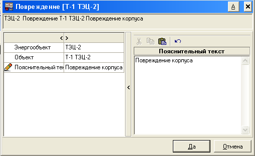
The data of additional logs are stored in the EZH database and contain information about the parameters and time of the event, the power facility, an explanatory part, data about the person who made the entry:
The developed journals are fully integrated with electric circuit. Automatic transition from a log entry to a schema element and vice versa is provided. It is also possible to work logs without schema.
All journals allow you to generate reports in Word format
Power Supply Change Log
The power supply change log allows you to keep track of changes in the power supply of consumers.

Power Supply Change Log Form
Log of registration of technological violations
In the journal of technological violations (TN) are recorded:
- Time of occurrence of TN
- The object of the occurrence of TN
- Number of de-energized transformer substations, substations, healthcare facilities, heat supply
- Disconnected power
- Time to eliminate the TN commissioning the object
Data of the report on de-energized subscribers are formed automatically on the basis of pre-prepared directories of subscribers and analysis of the current network configuration.

Form of the log of technological violations

The form of recording the log of technological violations
Journal of consumer applications for power failure.
To organize the process of registering consumer applications in the DIS, an appropriate module has been developed that allows you to record information about the complete or partial loss of power supply using corporate information systems formed at enterprises.

Consumer Application Log Form

Consumer Request Log Record Form
Log of defects and problems with equipment and the progress of their elimination
A module for registering defects and malfunctions with equipment, fully integrated with the electrical circuit, has been developed. At the same time, an automatic transition from the record to the circuit element and back is provided.
The module provides the ability to select records by:
- the planned date of elimination of the defect (indicating a specific date or indicating a period),
- department responsible for troubleshooting
- all unrepaired defects, defects whose elimination period has expired;
The module allows you to postpone the deadline for fixing a defect.

Defect log form 
Defect log entry form
Security and legal aspects
All changes to the log are entered on behalf of the dispatcher who took over the shift. Forgery and retroactive modification of records in electronic journal excluded. For insurance against software failures, it is possible to maintain a hard copy (print) simultaneously with logging entries.
Connection of telesignaling / telecontrol
The dispatching information system can be considered as constituent part OIC (top level) in which support is implemented operational switching and there are ample opportunities for integration.
The software has a built-in ability to receive teleinformation and telemetry, as well as telecontrol power facilities through the OPC industrial software interface. This programming interface is supported by many modern complexes telemechanics, as well as OIC / SCADA systems.
The exchange of such complexes is carried out without additional programming. In the case of using information from systems that do not support OPC, docking can be carried out on a contractual basis by Modus developers or another contracting organization (development of an appropriate OPC server is usually optimal).
Thus, the software package can be considered as an integral part of the OIC (upper level), in which support for operational switching is implemented.
TREI GmbH LLC, Penza
The article discusses an automated system for dispatching control over the processes of electricity distribution in the electrical network at JSC "MC TMK" using mnemonic diagrams. The structure of the system and the main technical solutions.
Energy is one of the strategically important branches of our industry, the basis of the country's economic independence and security. Today, the energy industry is on the verge of transformation. In this regard, the effective management of energy capacities and energy distribution is very important. great importance. Increasing the efficiency of generating capacities, as well as establishing optimal distribution modes are of great importance and make it possible to reduce the cost of energy, as well as to obtain maximum sales of products. In such a situation, one of priority areas improving the modes of management of energy facilities is the construction of modern automated control systems for production processes (APCS). At many enterprises, systems are being introduced that allow for the efficient management of energy capacities.
Currently being developed in Kazakhstan (Ust-Kamenogorsk) the automated system of dispatching power supply control of JSC "MC TMK" using a mnemonic diagram (abbreviated name ASDUE) is a similar system of effective control.
The developed power supply dispatching control system is created in order to increase the efficiency of managing the processes of power distribution in the electric network, reduce the time to restore the power supply to the consumers of the plant after emergency shutdowns, increase the productivity of operational personnel in scheduled work and provide:
Reflection of the actual position of the oil and vacuum circuit breakers of the power supply system of the plant on the mnemonic diagram and the dispatcher's workstation;
Virtual control of the symbols of disconnectors, load switches, separators, short circuiters on the mnemonic diagram and dispatcher's workstation with fixing the time and the basis of their switching;
Management of grounding symbols of lines and electrical equipment on the mnemonic diagram and the dispatcher's workstation with fixing the time and the basis of their switching;
Control of the consumed current on the input cells and outgoing lines on the dispatcher's workstation;
Remote control of oil and vacuum circuit breakers at the plant's facilities from the dispatcher's workstation;
Warning and emergency signaling from objects: generalized, AVR, AR trips, display of electrical protection trips;
Display of information about the emergency shutdown of the switch on the dispatcher's workstation;
Preservation for a month of all events on the mnemonic diagram and fixation time with the possibility of printing;
Recording and preservation within a month of operational telephone conversations of the dispatcher on each line with time fixation and with the possibility of printing;
Visualization of the scheme of the electrical network of the plant and the main controlled parameters on the mnemonic diagram for collective use.
Rice. 1. Three-level ASDUAE system
System Structure
The electrical network of the plant is a geographically distributed structure, consisting of stations and substations with electrical equipment installed indoors, as well as on open switchgears. The basis for the construction of ASDUE is the principle of constructing a logical part based on programmable logic, that is, a TREI-5B-02 programmable controller is used to implement the control, measurement and control algorithm. The programmed logic of the algorithm is implemented by polling the actual state of the input signals, comparing the values of these parameters with those specified in the program, and when the dispatcher confirms the actions performed by issuing control output signals.
In terms of its architecture, ASDUE is a three-level distributed computing system divided by functions performed (Fig. 1).
The first level of the hierarchy is the means of instrumentation installed directly at the local facilities of the plant's electrical network, which are part of the structure of this project.
The second level of the hierarchy is formed by controllers. This level is characterized by geographical and functional distribution of hardware.
The third level is the level of ODS (operational dispatch service, automated workstations of the dispatcher, operational and managerial personnel). It is built on the basis of client-server technologies.

Rice. 2. Complex of technical means
System Composition
In accordance with the purpose of ASDUAE, it contains:
Information and control system of the plant's electrical network;
Mnemonic diagram of the collective use of the dispatcher of the plant for power supply.
The main tasks set before the ASDUE system are control of the actual position of oil and vacuum circuit breakers VM (426 points), control of the operation of protection devices, control of the consumed current, control of the symbols of electrical devices on the mnemonic diagram. Ensuring the required reliability of the system functioning (redundancy of master modules, the possibility of switching from remote to local control). Possibility to replace controller modules without stopping the system. Software and hardware diagnostics of the controller and input signals. Building functionality systems at the lowest cost through the use of a single series of controllers. Display of actual operational and archived information on a general mnemonic diagram, mnemonic diagrams of local objects, real-time trends and history trends, printed reports. The proposed technical solutions ensure the integration of ASDUES as an integral part into the overall network of the plant.
ASDUE is a set of control cabinets and auxiliary equipment, namely:
Cabinets with microprocessor controllers are designed to collect and process information from the structural elements of the plant's electrical network and remote control of electrical switching devices (VM) from the automated workstation (AWS) of the dispatcher;
Cabinets with devices for communication with objects (USO) are a physical and logical continuation of cabinets of microprocessor controllers with the implementation of similar functions of control, measurement and control;
Cabinets with power relays and current converters are designed to be connected to high-voltage cells in order to ensure control of oil circuit breakers of cells from microprocessor controllers and USO, as well as output measured current signals to the controllers;
The LAN local server cabinet is designed to collect information from system microprocessor controllers and subsequently provide information on the status, execution of control actions and malfunctions of the technological equipment of the plant's electrical network on the mnemonic diagram and the dispatcher's workstation. The local server is connected to the general computer network of the plant to view technological information on remote computers and saving an archive database with a depth of 1 year on a common server of the plant.
The local server cabinet includes the following systems:
Automatic digital recording of audio information "SPRUT-7A-7", which allows recording audio information from analog-digital communication channels and registration of incoming (AON function) and outgoing numbers, date, time and duration of a communication session;
The PLI 8-16 video information display system controller generates a split-screen image for it and controls the operation of the entire display system equipment complex.
The video information display system based on four SYNELEC C50X-BB-SL video cubes with a diagonal of 50’’ is designed to visualize (display) the actual configuration of the plant’s electrical network, operational information in real time, namely:
Current consumption by the main consumers of the plant;
The state of switching devices of the electrical network;
Displaying the process of performing operational switching by operational personnel (dispatcher, duty officer);
Display of emergencies that occur in the electrical network;
Control of withdrawal for repair, and preparation of equipment for repair;
Control of stationary and portable grounding.
Top-level software implemented: iFIX Plus SCADA Pack Server Version 3.0 (unlimited points), iFIX Standard HMI Pack Runtime Version 3.0 (unlimited points), iFIX iClient Runtime Version 3.0, Nautsilus OPC server (USB). Windows 2000, SP3 software is installed on the video cube controller, on the Windows SERVER 2000 server, on Windows XP Pro, Sp2 workstations.
Main technical solutions
Enlarged diagram of a complex of technical means
As already mentioned, ASDUAE is a three-level distributed system. The second level of ASDUAE provides the following functions: automated control of actuators of oil circuit breakers VM; primary processing and normalization of signals from measuring current transformers, it is built on the basis of Trei-5B-02 controllers from TREI GMBH LLC, Penza, License No. 19-02. The upper level implements the functions of the human-machine interface and is based on software products from General Electric. On fig. Figure 2 shows an enlarged diagram of the complex of technical means of ASDUE. As can be seen from the diagram, the Control System has a distributed structure and consists of:
Mnemonic schemes for collective use of the dispatcher of the plant for power supply;
local server;
Dispatcher and engineering stations (AWP 1 and 2);
ShK1-SHKn.. system controllers included in remote USO and cabinets with power relays and current converters. Communication between the controllers is carried out via Ethernet 100 Mb/s, which provides a high exchange rate to obtain the necessary information.
The main controller and SCADA iFIX Plus Pack Server communicate via a 100 Mb Ethernet industrial network. Stable operation of the collective mnemonic diagram, local server and operator stations is provided by sources uninterruptible power supply installed in the operating room.
The main controller SHK0 is responsible for communicating with the local server and monitoring the state of the plant's electrical network equipment through the interrogated SHK system controllers and remote USOs included in them. The main controller transmits the received data for display on SCADA, and through it the supervisory control of system controllers is carried out (changing settings, operating modes, priorities). To improve the reliability of the ASDUE, and to prevent the loss of communication between local network objects and the main controller, redundancy of the processor part and power supplies is used on it. This configuration will increase the survivability of the system. Structural scheme shown in fig. 2 gives an idea of the distribution of technical means at the facilities of the plant's electrical network. AT this case, the use of the RS-485 (STBUS) and Ethernet protocol makes it possible to expand the system and save on cable production when connecting remote objects. The server performs the functions of collecting, storing, archiving and issuing operational data. The operator's station provides for remote (supervisor) control of VM switching electric devices. The choice of SCADA iFIX facilitates the integration of the APCS under construction with existing automation tools. If necessary, it is possible to transfer technological data to a common server of the plant. The storage of technological settings is carried out in the non-volatile memory of the controller, which allows the system to remain operational in case of failure or lack of communication with the local server.
This configuration of the system allows: to reduce the recovery time of the system due to modularity (mezzanine modules) and quick replacement of its elements. Replacement of a single failed module or instrument can be carried out without interrupting the operation of the system; ensure good reliability indicators due to redundancy and duplication of the most significant components of the system. In particular, if one of the master modules fails or if communication with one of them fails, a transition will be made to the backup.
Short description
technical components
microprocessor
controller
The TREI-5B-02 device is designed for local and distributed systems of automatic control and process control on industrial enterprises with normal and explosive production.
The product has a certificate of approval of the type of measuring instruments No. 2641 (Kazakhstan No. 1503), TUV certificate, permission to issue and use No. 507-EV-1Ya1, the manufacturer has a certificate of compliance with the quality management system ISO 9001 No. ROSS RU. IS50.K00019. A serial interface based on RS-485 and a wide range of I/O modules allow you to create distributed, multi-level and multi-functional systems. The unified communication protocol ST-BUS simplifies programming and collection of information from I/O channels. All input and output data structures are unified. The processor part of the controller is a PC compatible computer with the necessary set of external devices. QNX real-time operating system and IsaGraf development environment. The TREI-5B-02 controller design is based on the Euromechanics 3 U format. The housing is available in open or closed design, optionally with DIN rail mounting. Modules with size printed circuit boards 100x160 mm have on front panel indicator light and a 48-pin connector on the back for power, serial, and I/O connections. The basic interface of the controller is a ST-BUS serial interface based on RS485, which allows you to create distributed systems with a physical line length without repeaters up to 1200 m. The maximum interface speed is up to 1.25 Mbod. I/O modules have their own Pic-processor and can work autonomously. The collection of information via the ST-BUS communication protocol from the I/O modules is carried out by the M701E master module or an industrial computer with a serial RS485 interface. The range of I/O modules allows you to create multi-channel and multi-functional systems. The universal module, completed with mezzanine modules of the TREI-5 series, has a complete set of connected devices. Multi-channel modules of the same type for discrete and analog input / output, pulse input provide up to 4000 channels per master module.
The master module performs the main computing functions of the controller.
In its composition it contains:
Base board of the master module;
Processor module with Pentium processor;
Ethernet 10/100 communication adapter board;
Galvanically isolated RS485 ports;
ST BUS controller;
Non-volatile static RAM;
Flash disk;
IR port;
watchdog timer.
The following I/O modules are installed in the chassis (all I/O modules are of general industrial design):
The ION M732U module is a versatile 8-channel I/O module.
The specific channel type is determined by the installed mezzanine. The mezzanine is a block of primary signal conversion mounted on the module. IDIG-24VDC type mezzanines are used for connecting 24VDC discrete signals, and IANS 0-20 mA mezzanines for connecting 0-20 mA analog input signals;
Modules M754D - 32 discrete input channels 24VDC;
Modules M754O - 32 discrete output channels 24VDC;
Modules M743D - 16 discrete input channels 24VDC;
M743O modules - 16 discrete output channels 24VDC.
All channels are isolated. In addition to the I/O modules and the master module, the chassis is equipped with a P701 A power supply module with a power of 40 W and provides power to the controller elements. For analog input mezzanines, the main reduced error does not exceed 0.025%. For analog output mezzanines, the main reduced error does not exceed 0.1%. The conversion is carried out by a 16-bit DAC. Detailed description modules are presented on the TREI-GmbH website.

Video information display system
The proposed solution uses projectors built using DLP™ technology from Texas Instruments. DLP™ technology is the de facto standard for video walls due to the lack of pixel burn-in associated with plasma panels. The DLP projector's manufacturer-claimed MTBF is at least 100,000 hours (more than 10 years of continuous operation). The proposed solution is based on XGA (1024x768) Clarity-Synelec video cubes. The video cubes have a built-in processor that allows processing the digital information stream at a speed of up to 16,000 Mb/s, which is tens of times faster than similar systems. Unlike built-in splitters - simple splitters of the incoming signal, Clarity-Synelec video cubes are a full-fledged multi-channel digital processor. Two DVI inputs allow two scalable and movable information windows to be displayed simultaneously and independently. The presence of two independent inputs at the video cube ensures high reliability of the equipment: if one video information processing channel fails, the second channel remains operational. To receive top quality images in Synelec video cubes use ultra-black anti-reflective translucent screens. Today they are the highest quality and high-tech translucent screens on the world market. These screens are offered by Clarity-Synelec for the highest requirements for image quality (graphic resolution, clarity, contrast). They are characterized by a wide field of view and the absence of glare even in strong illumination from extraneous light sources (the ultra-black screen absorbs 99.5% of the light from external sources). According to their properties, the screens provide the practical absence of inter-screen gaps, and, consequently, the most comfortable conditions for observation. Microscopic optical elements provide high uniformity of brightness over the entire surface of the screen, Wide viewing angle: 180 degrees - horizontally, 180 degrees - vertically. Ensuring the best clarity and contrast when displaying a signal with high graphical resolution enables effective cleaning contamination (most lenticular-raster optical translucent screens have a microlens outer surface and allow you to clean dirt only with compressed air. The screens have a smooth protective outer surface that allows effective cleaning). The video wall controller, the PLI 8-16 network controller, is a powerful control system for real-time display of rich computer graphics and video images. It combines a modern hardware platform and software to ensure high performance, reliability and ease of use.
A video wall can combine up to 80 video cubes. The PLI 8-16 controller generates a split-screen image for it and controls the operation of the entire complex of display system equipment. Due to the features of the controller architecture, digitization and display of video sources occurs in real time without loading the central processor and without loss of information.
The controller uses the most Hi-tech and protocols. The DVI digital protocol was chosen as the interface for transmitting the displayed information. This solution made it possible to get rid of noise, interference, frequency and phase distortions of the signal, which are typical for analog data transmission channels. Due to the absence of analog information transmission channels in the system, the image is of excellent quality and stability.

The PLI 8-16 controller allows you to launch any application from the network by displaying it in a window or on the entire split screen, that is, as required by the display script. Applications from a UNIX network can also be launched and shown on a split screen in the same way. The number of windows with applications is practically unlimited. Each window can be scaled, moved around the video wall screen, or enlarged to fit the entire screen. The controller is easy to operate and does not require any special skills from an operator familiar with the operation of Windows. Distinctive features of the PLI 8-16 controller are:
An upgraded hardware platform that allows you to build split screens up to 80 video cubes using one PLI controller. When using more complex configurations, the size of the video wall is not limited;
High-performance graphics processors with digital outputs that provide signal display without noise, distortion and interference;
Ability to work under Windows and Linux operating systems. Cross-platform software allows the controller to be used both in Windows and Unix networks, and in mixed networks;
Versatility and multitasking. The controller can simultaneously execute user applications, digitize video signals, import information from the local area network and display the results of work on the video wall in the form of freely movable and scalable windows;
Flexibility and scalability. The controller is easily reconfigured to solve a variety of tasks and can be expanded if necessary to expand the functionality of the system or the size of the split screen. The industrial version of the controller allows it to be installed in a standard 19'' rack cabinet, which provides increased noise immunity and improved ventilation of computer components.
The Clarity-Synelec PLI 8-16 network controller allows you to:
Summarize the resolutions of individual video cubes, providing an extremely high graphic resolution of a split screen (for example, for a video wall in a configuration of 2x2 video cubes, the resolution of a split screen is 1536x2048 pixels);
Work under Windows and Linux;
Execute local programs (for example, SCADA applications used by the customer);
Work with network databases;
Display copies of windows of network applications or copies of monitors of network workstations on the video wall;
Work with any image as with a normal Windows window: move, scale, minimize or maximize up to the size of the entire split screen;
Manage display scripts (including from remote workstations);
Generate, save and call scenarios required for display in a given period of time (for example, in different operational situations, normal / emergency);
Perform automatic monitoring of equipment with display of device status (including those on remote workstations);
Generate error messages, failures and malfunctions, perform predefined actions corresponding to each described problem (change the script, turn off and turn on the lamps, etc.);
Track given messages in a computer network and serial ports, perform predefined actions corresponding to each described message (part of the message being searched can be used as a variable for the action being performed);
Perform specified actions on a schedule (for each action you can set: time of day, days of the week, dates);
Save as a file an instant "snapshot" of the image on the entire split screen.

Rice. Interaction of logical subsystems at the time of drawing generation
Brief description of software components
As mentioned above, the TREI-5B-02 controller is a PC compatible programmable logic controller. This controller is running operating system QNX. The architecture of this operating system is designed specifically for use in real-time systems, which makes it the most optimal for use as an operating system for controllers. The operating system image and the files required by the controller are located on a flash disk or disk-on-chip. The ISaGRAF target task is running on the controller, which polls I/O modules and executes algorithms. The target task uses a configuration file containing a description of the algorithms and a description of the hardware configuration of the controller. The configuration file is prepared using the ISaGRAF software package. ISaGRAF tool CASE system for technological programming of controllers. Developed by CJ International. ISaGRAF is full support for all languages of the IEC 1131 3 standard. The development environment provides a complete set of tools for interactive creation of programs, their effective debugging, documentation and archiving of projects.
The upper level of the process control system is based on the iFIX SCADA package from General Electric. This software package includes both means for processing, accumulating and displaying information, as well as configuration tools that allow you to configure system components in accordance with the requirements of a particular object. Communication between the controller and the SCADA system is provided by the Nautsilus OPC server, twisted pair is used as the medium, and the transport protocol is Ethernet.
Specialized software
For the PLI 8-16 controller, a specialized software package Com.Base is supplied, which is an integrated multi-user control system for video wall equipment and the process of displaying information. Com.Base was developed by Synelec Telecom Multimedia as a universal software package that provides a single convenient and understandable user interface for automated management of all the variety of equipment and processes inherent in professional display systems. The controller architecture and software provide seamless integration into an existing computer network. The use of TCP/IP as the main communication protocol for all devices and modules of the system allows for remote diagnostics and system administration, including via the Internet. Additional software can be installed to remotely manage the network or host computers and share network resources. Synelec's full-featured Com.Base software provides the dispatcher with a comprehensive set of video wall management tools. Due to its simplicity and friendly user interface, Com.Base provides effective control over the system at three main stages of system operation: a) system configuration, b) system operation, c) system maintenance.
Let's consider the interaction of the main subsystems in the process of automatically creating a mnemonic diagram in the iFix environment, which is in the configuration mode: a start is given with the task of drawing a picture, and the SOLOMON block begins its work. Its goal is one of the primary ones: preparation, control and maintenance of the basis of the object model of the invisible framework of the future circuit. The necessary data flows are requested through the HERMES communication intermediary, which, in turn, contacts the external information storage through the DARIUS subsystem, which supports the plurality and diversity of sources and converts data to a single internal standard. Now, to master a new type of storage, it is enough just to inherit a template from a specialized class and fill it with the implementation of access and processing. If necessary, information channels are encrypted and decrypted by the ARES block. An important role here is played by the abstract entity "ProClass", which is the main building material of the logic of object constructions. Its structure is not hardwired into the code, but is dynamically formed using the abstract factory pattern and initialization files, implementing concrete descendants. Thus, it becomes possible to make changes to classes in non-fields of the program code. The emphasis is on two components - the logic (the semantic content of the object) is highlighted and a set of scripts associated with it is delegated. Objects are created and initialized. Links and groupings are introduced into objects according to the created scheme. Optionally, a mechanism has been developed for automatically generating tag names, which is based on the logical position of the object and its environment. As a result, a collection of all task objects is prepared in a single repository.
In fact, the LEONARDO block works out three modes:
1_Preparation for the use of minimally indivisible graphical objects from the point of view of the system with the end result - a library of primitives ("Atoms"). The need for the stage is primarily due to the idea of weakening the close relationship with the SCADA environment used.
2_Based on the resulting library of graphic "atoms", more complex entities of the "Symbol" class are constructed - logically complete images of the appearance of pro-object instances. If necessary, their animation is activated. Each type of symbol is represented in the singular.
3_Using the temporary storage of symbol instances and the object field prepared by the SOLOMON block, the final creation of the mnemonic diagram elements and their placement in the figure is performed. The transfer of information between the blocks and here passes through a single center. At the end, the newly created drawing is saved and placed in the visual forms logical storage to be later used by the MEMPHIS user interface subsystem.
Before proceeding to the description of the mnemonic circuit and its capabilities, I will tell you the background - what prompted me to such a perversion.
I work in the dispatching service of a heating network company. In service, in addition to the heating networks themselves, there are pumping stations, boiler houses and heating points. Of course, these objects have distribution. devices. At first, there were no problems - there was a dispatcher of the electrical department on the staff of the service, who was engaged in "electricity", while the rest - heat engineers by education - "ruled" networks, boiler houses, etc.
Difficulties began after the reorganization of our Company. ETC dispatchers were reduced and all the operational work on electrical equipment was given to us - heat engineers. Yes, we remember something from the course of school physics, someone did not lose their knowledge after lectures on TOE in technical schools and universities, but still our specialization is not. We still, at times, "amuse" the guys from the power grids with our competence in these matters.
So the idea came up to make mnemonic distribution boards. devices of the objects we manage to visually see the state of the circuits electrical connections: what equipment is in operation/reserve/repair; what will turn off if “this” or “that” bus section is de-energized.
Since SCADA systems are expensive, and pirated software is not welcome at the workplaces of a large and serious company (and I don’t know how to work with them), it was decided to experiment in MS Excel, since I’m good with it. I agree that this can be compared to hammering nails with a microscope, but the result is quite acceptable.
Description of the mimic
This article contains a non-existent mnemonic diagram, which I compiled specifically for publication. It is labeled:
- two sources of external power supply (Substations No. 1, 2);
- two sections of tires 6 kV with a sectional switch;
- two sections 0.4 kV with a sectional;
- equipment: two transformers, pumps, steam and hot water boilers.
This is the minimum for an example. Of course, you can add other equipment.
The scheme implements primitive dynamics: when the operational state of the switches changes, the appearance of the scheme changes. In order not to write "a lot of bukaf", I will give screenshots.
Disconnected input from Substation No. 2

As you can see, sections 6 and 0.4 kV are de-energized.
The input from Substation No. 1 was disconnected, 1 section 0.4 kV was put out for repair

When drawing up the mnemonic diagram, I tried to take into account different variants its assembly, so that at the same time, the whole circuit reacts: switches, transformers, and equipment.
The mnemonic diagram was compiled in MS Excel 2013. The file format is .xlsx.
The pseudo-dynamics of the circuit is implemented using boolean functions and conditional formatting.
Here is an example of a function that determines the operational status of a 6 kV busbar section:
IF(AND(F33=$DD$3,F25=$DD$3,AC39=$DD$3),$DF$3,IF(OR(AND(F33<>$DD$2;AC39<>$DD$2);AND(F25<>$DD$2;AC39<>$DD$2);AND(F25<>$DD$2;F33<>$DD$2;AC39<>$DD$2));$DF$1;$DF$2))
If you find inaccuracies and gross errors - let me know in the comments.