Electricity distribution schemes inside residential buildings depend on the reliability of power supply, the number of floors, sections, the planning solution of the building, the presence of an underground floor and built-in enterprises and institutions (shops, ateliers, workshops, hairdressers, etc.). These schemes have general principle construction.
In every high-rise building an input-distribution device is installed to connect the internal electrical networks of the building to external supply lines, as well as to distribute electrical energy inside the building and protect outgoing lines from overloads and short circuits.
For the power supply of apartments, supply lines, consisting of horizontal and vertical (risers) sections, depart from the ASU. One or more risers can be connected to the horizontal section of each line. However, it should be borne in mind that in the event of a short circuit on one of the risers, the protection at the ASU will work and the supply line will deviate, while a large number of apartments will be without food. Therefore, in order to increase the reliability of the power supply of apartments, as well as for the convenience of performing repair work, a disconnecting and protective device should be installed on each branch to the riser. In addition to the lines supplying the apartments, intra-house lines supply the lighting of halls, stairs, corridors, as well as electric motors of elevators, pumps, fans and electrical receivers of the smoke protection system. A schematic diagram of the power supply of a 16-storey one-section residential building is shown in the figure.
As can be seen from the diagram, the building's electrical receivers are powered by two mutually redundant cables 1, designed for powering (in emergency mode) all its loads. If one of the supply cables fails, all electrical receivers are connected to the cable that remains in operation using switches 2 installed on the ASU panel. To protect the ASU panels from short circuits, fuses 3 are installed at the inputs.
To account for the consumption of electricity from electrical receivers for public purposes ( task lighting stairwells, basement, attic, house premises and power consumers, including elevators, and stairwells), a three-phase meter 5 is installed, switched on through current transformers 4.
To suppress radio interference, one noise-protective capacitor of the KZ-05 type with a capacity of 0.5 microfarads is installed on each phase of the inputs. Capacitors 7 are equipped with fuses 6 and are grounded.
The outgoing lines from the ASU are protected by automatic switches 8. To the risers 9 (section III) supplying the apartments, floor apartment shields are connected, which are installed in electrical cabinets 10 located on stairwells(OK). One 11 is installed for each group of apartments, which is connected to two phases and the neutral wire of the riser.
In the electrical cabinet, single-phase apartment meters 12 and group shields 13 with circuit breakers or fuses to protect apartment group lines.
Fans of the smoke protection system 14, control panels and evacuation lighting are connected to a special panel (section I), on which an ATS device (automatic transfer switch) is provided. Connecting this panel to two inputs up to switches 2 by means of an ATS always ensures its uninterrupted operation. From section II, the supply lines feed the elevator installations 15 and evacuation lighting.
Section IV is connected to section III through a circuit breaker 16 and electricity consumption meters, from which the common house premises are powered. From the V panel power sockets for harvesters and emergency lighting for the machine room of the elevators and the electrical room.

In each apartment, regardless of the number of rooms in it, for supplying lighting and household electrical appliances with gas stoves, as a rule, two single-phase groups are laid with aluminum wires with a cross section of 2.5 mm2. One feeds the general lighting, the other - sockets. Mixed power is also allowed, while the sockets installed in the apartment must be connected to different group lines. Where there are kitchen electric stoves, a third group line is provided for their power supply.
Typical project of a 17-storey residential building
EOM - power electrical equipment, electrical power networks and electric lighting of an apartment building.
This section of the project deals with power electrical equipment, electrical power networks and electric lighting of an apartment building.
The power supply of the main equipment, in terms of the degree of reliability, belongs to category II in accordance with the PUE classification and the requirements of SP 31.110-2003 and is carried out through two cable entries from an external power supply network with a voltage of ~ 380/220V alternating current frequency 50 Hz. Grounding system at ASU type TN-С-S.
The power supply of the facility is provided from the 0.4 kV switchgear of the designed free-standing distribution substation.
The input-distribution device of the ASU is powered by two mutually redundant cable lines brand APvzBbShp-1 2x(4x120). The cables are laid in a trench, in the ground at a depth of 0.7 m.
For distribution of power supply to power electrical equipment, lamps of the main and emergency lighting the project provides for distribution electrical panels ShchAV, ShchSS, PPN.
For the supply of electrical receivers of category I, the project provides for the installation of automatic input of the reserve.
To electrical receivers of the I category of reliability of power supply, according to SP 31.110-2003 tab. 5.1 include:
Safety lights;
Lift equipment;
Emergency lighting;
CCTV;
Fire alarm system;
Dispatching system equipment (ACS);
Security and communication systems;
pumping stations;
Fire-fighting devices (supply and smoke exhaust systems, smoke exhaust valves, fire extinguishing systems);
A source uninterruptible power supply provides autonomous power supply for at least 1 hour.
Power equipment.
The power supply network of power electrical equipment is carried out with cables of the VVGngLS 3x[S] brand, in PVC corrugated pipes on the ceiling, in floor preparation and in metal trays, in wall strobes and cable channels, in accordance with the technological plan for the placement of technological and other equipment.
In the event of a fire, it is planned to turn off the exhaust ventilation of the air by turning off the switchboard of the B1 system.
Nutrition ventilation unit produced by an independent line from switchboard B1. Smoke exhaust fans are controlled using control boxes of the Ya5000 type (or similar).
Passenger elevator control panel, supplied complete with equipment.
The operation of the pumps is controlled from the control stations included in the pumping units supplied complete with the equipment.
The operation of light-protective lights (ZOM) is controlled from the control panel included in the installation, supplied complete with the equipment.
Electricity of the net
The power supply network for household and technological sockets is carried out with a cable of the brand VVGngLS 3x2.5 V PVC pipes 20 mm in diameter.
Sockets are installed on the wall in accordance with the height marks indicated on the plan.
Blue - zero working conductor (N);
Green - yellow - neutral protective conductor (PE);
Black or other colors - phase conductor.
In accordance with clause 7.1.49 of the Electrical Installation Code, with a three-wire network, install socket outlets for a current of at least 10A with a protective contact, which must have protective device, which automatically closes the sockets when the plug is removed.
The daisy chain connection of the PE conductor is not allowed (PUE 1.7.144).
PVC pipe must have a certificate fire safety(NPB 246-97).
Electrical equipment and materials used during installation must have a certificate of conformity with Russian standards.
electric lighting
Electric lighting of premises is carried out in accordance with SP 52.13330.2011 "Natural and artificial lighting".
Group networks of working and evacuation lighting are carried out with a VVGng-LS 3x1.5 brand cable, in PVC pipes on the ceiling.
Group emergency lighting networks are carried out with a VVGng-FRLS 3x1.5 brand cable, in PVC pipes on the ceiling.
The project provides for a combined lighting system and the following types artificial lighting: working, emergency (reserve and evacuation) and repair. Mains voltage of working and emergency lighting - 220V, repair - 36V.
To accommodate automation and protection equipment for electric lighting, the project provides for the installation of a lighting panel for ShchO and emergency lighting for ShchAO.
The project uses luminaires with LED and fluorescent lamps.
The choice of fixtures was made in accordance with the purpose of the room and the characteristics of the environment, as well as in accordance with the terms of reference.
IN public spaces emergency lighting fixtures are used for emergency lighting at night.
Switches and switches are installed on the wall from the side of the door handle at a height of 1000 mm from the floor level.
The project provides for manual (local) lighting control, as well as remote control from the control room. To save electrical energy, automatic control lighting using motion sensors (on the evacuation stairs) and presence sensors (elevator hall and corridor).
The project provides for the installation of a system of obstruction lights (ZOM) on the roof.
Electric shock protection
To ensure the safety of people, the working documentation provides for all types of protection required by GOST R 50571.1-93 (IEC 364-1-72, IEC 364-2-70) "Electrical installations of buildings. Basic provision". Protection against direct contact is ensured by the use of wires and cables with double insulation, electrical equipment, apparatus and lamps with a degree of protection of at least IP20.
All metal parts of electrical equipment not normally energized metal constructions for the installation of electrical equipment, metal pipes of electrical wiring are subject to protective earth in accordance with the requirements of the PUE for networks with dead-earthed neutral point 1.7.76 PUE ed. 7.
Protection against indirect contact completed automatic shutdown damaged section of the network with overcurrent protection devices and the implementation of a potential equalization system. For protection against low fault currents, reduction of insulation level, as well as in case of breakage of zero protective conductor device used protective shutdown(RCD).
Electricity metering
Commercial metering of electricity is carried out at the border of the balance affiliation in the ASU.
as sensors input control electricity, use three-phase electronic meters, transformer-type Mercury 230 ART02-CN 5-10A, having a telemetry output for connection to ASKUE (the type of meter should be additionally agreed with the services).
Lightning protection system
Object classification.
Object type - Multi-apartment residential building. Height 45 m. The project adopted category III lightning protection in accordance with SO 153-34.21.122-2003.
III level of protection against direct lightning strikes (LLL) - reliability of protection against LL 0.90. The complex of designed facilities includes a protection device against direct lightning strikes (external lightning protection system - LPS) and devices for protection against secondary lightning effects (internal LPS).
External lightning protection system
Use as a lightning rod metal mesh, made of galvanized steel wire with a diameter of 8 mm (section 50 sq. mm). Use fittings Art. f8 GOST 5781-82. Lay the mesh on a layer of insulation, on top of the roof screed. The cell step is not more than 15x15m. Connect the grid nodes by welding. All metal structures located on the roof ( ventilation devices, fire escapes, drain funnels, fencing, etc.), connect to the grid by welding rods Ø 8 mm; length of welded seams - not less than 60 mm. All protruding non-metallic structures are also protected with a wire laid from above along the perimeter of the structure and connected to a lightning protection mesh.
Down conductors are located along the perimeter of the protected object. Use galvanized steel strip 25x4 as down conductors. The location of down conductors is shown on the plans. Down conductors will connect horizontal belts at elevations +12.00, +27.00 and +39.00m.
As a ground conductor, the project adopted reinforcement of a reinforced concrete foundation, connected by welding with a steel strip 50x4 in accordance with GOST 103-76. The lightning protection grounding strip is laid around the task, at a depth of at least 0.7 m from the ground surface. The soil is loamy with a resistivity of 100 ohm*m. The length of the horizontal grounding D = 115.6 m.
Estimated resistance to current spreading, not more than R=4.0 Ohm;
System material - Steel.
All connections are to be welded. Provide anti-corrosion coating of all exposed elements of the lightning protection system. To protect the ground loop from soil corrosion, cover its elements bituminous mastic MBR-65 (GOST 15836-79), not more than 0.5 mm thick.
Connect the lightning protection grounding conductor to the GZSH at the ASU.
Protection against secondary effects of lightning.
To protect against the drift of high potential through external metal communications, they must be connected to the grounding conductor of the lightning protection system at the input of communications into the building. The connection is made with a steel strip with a section of 40x4 (GOST 103-76).
To protect people in elevator shafts from step voltages and touch voltages that may occur on the floor and lifting equipment, lay a circuit around the mentioned equipment in the shafts. The contour is made of steel strip 40x4. Contour to perform on the horizon +12.00 +27.00 and +39.00m. For potential equalization, metal frame parts lifting mechanisms connect with contours. Connect the elevator protection circuit to the GZSH.
All connections are to be welded.
Provide anti-corrosion coating of all elements of the lightning protection system. To protect the system elements from soil corrosion, cover its elements with MBR-65 bituminous mastic (GOST 15836-79).
Installation instructions for grounding pipelines:
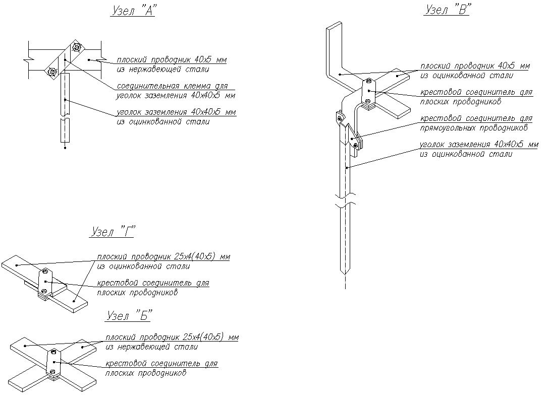
Grounding of metal pipelines should be carried out at the input from the side of the building, in places accessible for maintenance. Connect all external metal pipelines to the artificial ground electrode of the external lightning protection system. For connection use a steel strip 40x4.
For cast iron pipes sewers use a clamp outlet made of steel 08X13. Clamps to establish on stripped to threw. shine the pipe, followed by processing the junction with technical petroleum jelly.
Mounting points to perform in accordance with the instructions U-ET-06-89.
The contact resistance of the connection is not more than 0.03 Ohm for each contact.
Coordinate with Mosvodokanal the grounding of the water supply in accordance with UDC 696.6, 066356 p.542.2.1, p.542.2.5.
Grounding and potential equalization system.
Use the lightning protection ground loop as a re-grounding conductor.
Use the PE VRU bus as the GZSH bus.
Connect the external ground loop to the GZSH. For connection, use a steel strip St.50x4.
The connection is made by welding. For strip steel conductors, weld length 100 mm, height 4 mm. Connections with pipes should be made in accordance with the nodes shown on the drawing or in accordance with the requirements of the type album of series 5.407-11 ("Grounding and zeroing of electrical installations). Places of external connections and external steel connecting conductors should be painted with MBR-65 bituminous mastic.
Perform potential equalization according to the diagram (see sheets 41 and 40).
Lay the potential equalization conductors that are not part of the cable openly, with fastening to the building structures using metal brackets. Determine the distance between the fasteners during installation. Laying through the walls should be carried out in sleeves with a diameter that ensures the free passage of the conductor. Hidden laying is allowed in fire hazardous, hot, damp rooms.
List of working drawings of the main set of the EOM brand:
- 1. General data
- 2. Electrical circuit diagram single-line input-distribution device ASU
- 3. List of electrical consumers and calculation of electrical loads
- 4. Typical nodes
- 5. Electrical circuit diagram of a single-line switchboard SCHSS1
- 6. Electrical circuit diagram of a single-line switchboard DF
- 7. Electrical schematic diagram of a single-line switchboard SCHSS3
- 8. Electrical circuit diagram of a single-line switchboard of the switchboard ShchSS2 and Ya5111
- 9. Electrical circuit diagram of a single-line switchboard of a floor distribution switchboard
- 10. Schematic electrical circuit single-line switchboard switchgear
- 11. Scheme for connecting active electricity meters to current transformers
- 12. Electrical circuit diagram of a single-line switchboard of a storey ATS
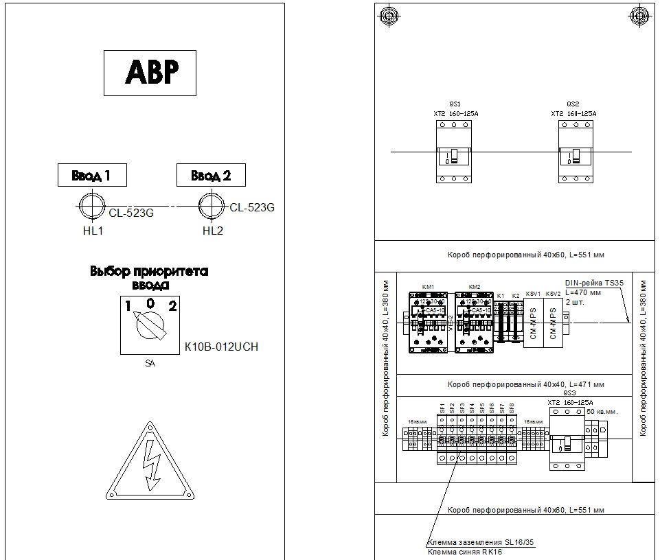
- 13. Assembly diagram. General view of the AVR
- 14. Assembly diagram. General view of the UERM escape stairs
- 15. Scheme electric control lighting of the elevator hall and corridors
- 16. Group lighting network of those. underground
- 17. Group lighting network of the 1st floor
- 18. Group lighting network 2 ... 17 floors
- 19. Power electrical equipment and group lighting network of the technical floor
- 21. Power electrical equipment of those. underground
- 22. Power electrical equipment of the 1st floor
- 23. Power electrical equipment 2 ... 17 floors
- 24. Grounding and lightning protection of the building
- 26. Scheme of the main potential equalization system of the building
- 27. Plan for the entry of cables from the trench into the network building 0.4 kV (section)
- 28. Plan for the entry of cables from the trench into the network building 0.4 kV
Electrical schematic diagram of a single-line switchboard ASU
Typical Mounting Assemblies

Schematic diagram of a single-line electrical switchboard of the switchboard ShchSS2 and Ya5111

Scheme for connecting active electricity meters to current transformers

General view of the floor switchgear (UERM)

Escape staircase lighting control

Group lighting network. Tech plan. underground


Grounding and lightning protection. Tech plan. underground
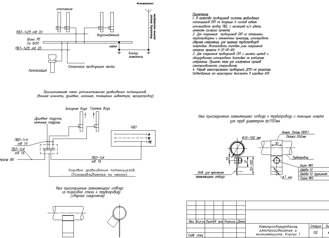
Scheme of the main potential equalization system of the building
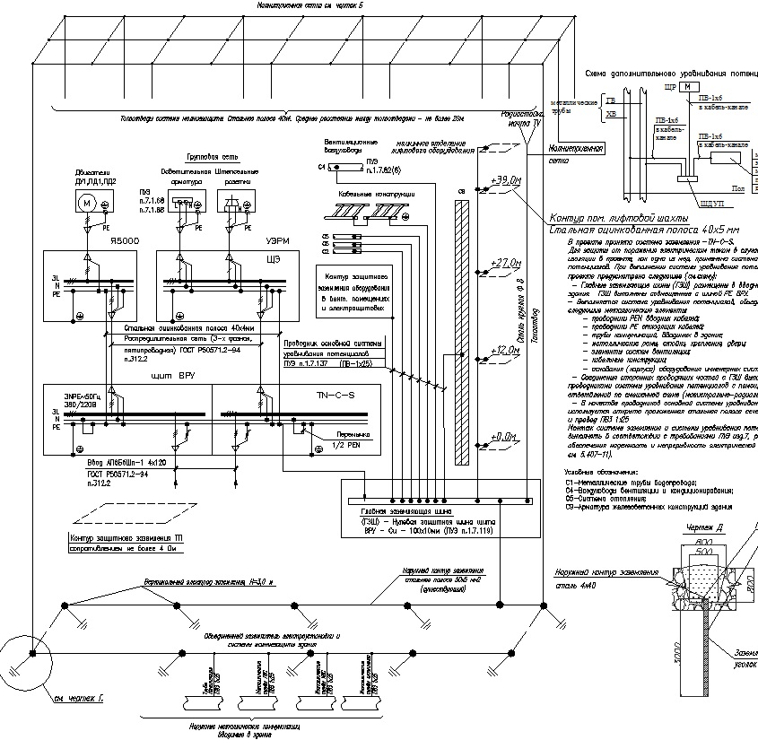
Grounding and lightning protection. Roof plan.

Plan for the entry of cables from the trench into the 0.4 kV network building
In order to properly understand the various power supply schemes for residential buildings, you need to know about the three categories of ensuring the reliability of the power supply of electrical installations. The simplest category is the third. It provides for the power supply of a residential building from a transformer substation through one electric cable. At the same time, in the event of emergency interruption in the power supply of the house should be less than 1 day.
With the second category of power supply reliability, a residential building is powered by two cables connected to different transformers. In this case, if one cable or transformer fails, the power supply to the house for the time of troubleshooting is carried out through one cable. A break in the power supply is allowed for the time necessary for the on-duty electrical personnel to connect the loads of the whole house to a working cable.
There are two types of home power from two different transformers. Either the loads of the house are evenly distributed over both transformers, and in emergency mode they are connected to one, or one cable is used in the operating mode, and the second is a backup. But in any case, the cables are connected to different transformers. If in switchboard at home two cables are laid, one of which is a reserve one, but it is possible to connect these cables to only one substation transformer, then we have only the third category of reliability.
With the first category of power supply reliability, the residential building is powered by two cables, as well as with the second category. But when a cable or transformer fails, the loads of the entire house are connected to a working cable using an automatic transfer switch (ATS).
There is a special group of electrical receivers (smoke removal systems in case of fire, evacuation lighting and some others), which must always be powered according to the first category of reliability. For this use backup sources power supply - rechargeable batteries and small local power plants.
According to existing standards for the third category of reliability, electricity is supplied to houses with gas stoves no more than 5 floors high, houses with electric stoves with less than 9 apartments in the house and houses of gardening associations.
Houses with gas stoves with a height of more than 5 floors and houses with electric stoves with more than 8 apartments are subject to electricity supply according to the second category of reliability.
According to the first category of reliability, it is mandatory to supply heat points with electricity apartment buildings, in some houses and elevators. It should be noted that in the first category, electricity is mainly supplied to some public buildings: these are buildings with more than 2000 employees, operating rooms and maternity wards of hospitals, etc.
The figure shows a power supply diagram for a four driveway house, powered by the second category of reliability with a backup cable. The switching of the supply cables is carried out by a reversing knife switch having positions "1", "0" and "2". In position "0" both cables are disabled. From circuit breakers QF1 .... QF4, the lines that go along the access roads are powered. vertical risers from which food is taken to the apartments. General household loads: lighting of stairs, basements, lamps above entrance doors the entrances are fed by a separate group containing its own electricity metering.

Rice. 1. Power supply scheme of an apartment building
Depending on the number of apartments in the house, all electrical equipment can be placed in one electrical cabinet or in several. What the electrical equipment of switchboard residential buildings looks like is shown in the photographs. In photo 1 - introductory devices and metering units. In photo 2 - a reversing knife switch with fuses. On photo 3 - circuit breakers on outgoing lines.


If the school had a subject: “The basics of the power supply of our home”, then accidents caused by the failure of various power switches and disconnectors on power lines and in transformer substations would have happened much less frequently. From childhood, we are taught to wash our hands before eating and are told how to cross the road correctly. But no one teaches us that if the lights go out in the apartment, then all powerful electrical appliances should be immediately disconnected from the network: irons, heaters and electric stoves.
For example, if a power outage occurred as a result of a blown fuse in the electrical panel of a house, then in order to restore power supply, electricians will need to turn off the breaker, replace the fuse, and turn the breaker back on. The "life" of all switching devices depends very much on the magnitude of the switched load.
If all the residents of the house disconnected their electrical appliances from the network when the voltage went out, then such inclusions would occur at much lower currents and the circuit breakers would last much longer.
In our example, when electricians turn off the breaker, then in a two-phase circuit with unburned fuses, at the moment the contacts are disconnected, a bright flash can be observed - an arc will flash for a fraction of a second, from which the contacts will gradually burn out.
In multi-apartment buildings, energy input and distribution systems generally depend on the building itself (the amount of electrical equipment in it to ensure its life). Let's try to understand the devices of such systems.
Energy distribution in an apartment building with a TN-C system
TN-C is an outdated system, but it is actively used in old houses. This is a four-wire system consisting of three voltage phases and a combined neutral and working conductors (L1, L2, L3, PEN). In this PEN system, the conductor is not subject to splitting and in this form it comes to the consumer. It is also worth noting that quite often the phase wires are given the name A, B, C.
As a result, with such a power supply system, with a single-phase connection, the consumer is connected with two wires (L, PEN), and with a three-phase connection with four (L1, L2, L3, PEN).
A power cable comes from the substation to the house, laid underground. The cable enters the input box connected to the switchboard:
Vertically laid risers will already depart from it. On each floor, floor shields will be connected to the risers, from which the apartments will be supplied with electricity.
Inputs can be made different ways, it directly depends on the number of storeys and the size of the house, on the cable laying system (in the collector or in the ground). Why is that? Yes, because the load of a house with 100 apartments will be significantly lower than a house with 500 apartments. Moreover, the power supply requirements of, for example, a five-story building are relatively small - there are no elevators in the house and there is no need to install additional pumps to maintain water pressure, which can not be said about a 30-storey building, where it is impossible to leave elevators and water supply pumps without power.
It is for these reasons that in large houses not one, but two or more power supply cables can be introduced. The distribution of electrical energy between general house loads (elevators, entrance lighting, pumps) and apartments is a rather complicated and time-consuming task. The distribution is carried out using complete electrical devices, the mounting methods, dimensions and installation locations of which are coordinated with the structures of the houses.
Let's look at options for connecting apartments to risers in multi-apartment buildings with a TN-C system. The riser has four wires - three phases and one PEN conductor, indicated in the diagram as A, B, C and PEN:

Between the phases (A-B, C-B, C-A), the voltage will be 1.73 or more than between any of the phases and the neutral conductor (zero). From here we calculate the voltage between phase and neutral - 380 / 1.73 \u003d 220 V. Two wires enter each of the apartments - phase and neutral. The current in both of these wires will be exactly the same.
They try to connect the load (in our case, apartments) evenly to different phases. In figure a), out of six apartments, two are connected to each phase. Uniform connection makes it possible to reduce and avoid phase imbalance.
In houses of old construction, combined electrical cabinets were sometimes used instead of floor shields. An example of such a cabinet is shown below:

This cabinet has compartments with separate doors. In one compartment there are plates with apartment numbers, switches and circuit breakers. In the other, meters, in the third, low-current devices such as telephones, television antenna networks, twisted pair intercom, internet and other devices.
In such a floor shield, each apartment includes one switch and two automatic switches (the first for the general lighting line, and the second for socket outlets). In some versions of electrical cabinets, the presence of socket outlet with protective contact for connecting various machines (e.g. harvesters).
Energy distribution in an apartment building with a TN-C-S system
In a residential area, electrical wiring consists of an electrical input, a group electrical network, distributing energy from the switchboard throughout the room and, in fact, the switchboard itself. For each group of consumers, electrical wiring is carried out with a cable with a certain cross section and circuit breakers with previously calculated ratings.
Input and distribution devices
As mentioned earlier, the power cable coming from the substation goes to the VU (input device) or ASU (input switchgear). For an apartment building, their main difference from each other will be that the ASU has equipment for distributing energy throughout the building.
So, ASU is a set of protective devices (fuses, circuit breakers, and so on), devices and devices for electricity metering (electricity meters, ammeters, and so on), electrical equipment (tires, circuit breakers, and other devices) as well as building construction installed at the entrance to a building or residential premises, which include protective devices and metering devices (electricity meters) of outgoing electrical wiring lines.
You also need to remember that re-grounding lines are suitable for both the WU and the ASU, which means that the splitting of the incoming PEN conductor can only be done here.
When using the TN-C-S system, the combined PEN conductor coming from the substation must be split. The TN-C-S system will take place only after splitting from the side of the transformer substation. In modern floor shields, three-phase automatic machines and difautomatic devices are usually installed.
After the ASU or VU, electricity is supplied to the storey switchboards of an apartment building. When using the TN-C-S system, five wires (L1, L2, L3, N, PE) go to consumers.
And who will be interested a little about the VRU: