Probably, many have seen metal cabinets installed in entrances or separate rooms. These are the so-called input distribution devices, which provide the supply of electrical energy to each apartment. But not everyone understands how important the quality and correct assembly of this equipment, which are prescribed in the PUE, are.
Main switchboard and ASU - what is it in electrics: differences
At various facilities for the input and distribution of electrical energy, input distribution devices (ASU) are used. Also, these devices protect conductors and consumers from overloads in the network and short circuits.
The devices installed in the ASP account for the consumed electricity, and control of its uniform distribution is carried out. ASUs operate in electrical networks with a voltage of 200 and 380 Volts, with an alternating current frequency of 50 Hz.
ASU device:
- Housing (metal box);
- One-sided panel.
The device is assembled as follows. Mounted in a metal box, one-sided panel, various equipment is installed. This equipment includes an introductory machine, fusible links, electric meters, RCDs, difautomats or conventional circuit breakers.
Note! The connection of conductors in all ASUs and MSBs is carried out only through a deafly grounded neutral.
ASU may consist of several sections. Assembly is carried out in a suspended or floor state. According to the standards and rules of the PUE, the ASU must withstand the breaking current (shock), reaching 20 kA. The insulation of the conductors must withstand a voltage of 100 volts.
Introductory switchgears are assembled according to the design requirements provided by the customer. Since ASUs have found wide application, they can be performed in accordance with various climatic conditions.

It is worth noting that the ASU and the main switchboard will perform exactly the same functions. The main difference is that the main switchboard always comes first in any electrical circuit.
Main earth bar PE
Bus PE or main ground bus, is one of the components of a common grounding device for a particular object. This bus is used in electrical installations up to 1 kW. With its help, individual grounding conductors are connected, through which grounding and potential equalization are performed.
What is connected to the busPE:
- Ground conductor, which is connected to the ground electrode;
- Communication pipes made of metal;
- metal building frame;
- Parts of ventilation and air conditioning systems made of metal;
- Lightning protection system;
- Working ground conductor.
The installation of the GZSH is provided for by the rules of the PUE and is carried out inside the input switchgear or separately.
Note! If the main ground bus is located inside the device, then only the PE bus can be used in this case.
If the tire is installed separately from the device, then the convenience of its maintenance is a prerequisite.
Separately installed ground bus, the cross section should not be less than the supply PE or PEN conductor.
It is unacceptable to use aluminum products as GZSH. The tire must be made of copper or steel.
Structurally, this bus must necessarily comply with the rules and requirements of the PUE and have the possibility of individual maintenance of conductors.
PE conductor: characteristics
Correct and high-quality operation of the grounding system is its continuity. One of the elements of this circuit is the PE conductor. These conductors provide an inseparable connection of various parts of equipment and installations with the earthing system.
Types of protectivePE conductors:
- Provided (special);
- Open parts of electrical installations;
- Third party electrically conductive parts.
Specially provided conductors include the following types. Cores in multi-core cables, insulated and uninsulated wires running in the same sheath with phase conductors and permanently laid conductors with and without insulation.

The open conductive parts of electrical installations are aluminum cable sheaths, steel pipes in which electrical wiring is laid, metal trays and boxes.
Note! The connection of protective conductors to open parts of electrical installations is carried out only on condition that the connection of conductors to these structures is provided for by the technical specifications.
It is not forbidden to connect protective conductors to third-party conductive parts. These can be structures and structures made of metal (trusses or columns), reinforcing structures of buildings, industrial structures made of metal (lift shafts, rails, platforms).
As PE conductors, do not allow the use for equipment that is powered by other electrical networks, tubular wires and metal tube sheaths, pipelines with combustible and explosive mixtures and water pipes.
Separation of the PEN conductor into PE and N (protective and zero): rules
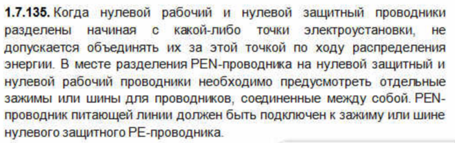
The supply network for various pantographs and installations should be 220 or 380 Volts. The grounding system in these installations must be TN - S or TN - C - S. According to the rules of PUE 1.7.135, separation of the neutral and protective conductors is mandatory in electrical installations.
What you need to separate the conductors:
- Power cable with PEN conductor;
- two tires;
- Jumper.
In order to carry out the separation of conductors, it is first necessary to lay a power cable with a PEN conductor.
After that, two tires (zero and ground) are mounted in the pantograph or ASU. A feature when mounting tires is that the zero bus must be mounted on special insulated brackets, and the ground bus directly to the device case.
Note! Separation of conductors is carried out only at one point. Their further connection is unacceptable.
This rule says that it is possible to separate conductors only in the input and further connection will be a gross violation of the rules.
After installing the tires in the device, a jumper of the same material and section is laid between them. The jumper can be one in the center or two at the edges.
The PEN conductor of the supply cable is connected only to the PE (grounding) bus. Both busbars must be designed to allow separate connection of conductors. Zero wires are connected to the zero bus, ground wires to the ground bus.
It is worth noting that such a separation of conductors provides high protection and high-quality operation of electrical installations and equipment.
GRSH and ASU - what is it in electrics (video)
ASU and MSB are technically complex equipment. Therefore, an untrained person should not mingle in their work. In the event of a malfunction, the best option would be to call an electrical specialist.
Correct and high-quality work is its continuity. One of the elements of this circuit is the PE conductor. These conductors provide an inseparable connection of various parts of equipment and installations with the earthing system.
Types of protectivePE conductors:
- Provided (special);
- Open parts of electrical installations;
- Third party electrically conductive parts.
Specially provided conductors include the following types. Cores in multi-core cables, insulated and uninsulated wires running in the same sheath with phase conductors and permanently laid conductors with and without insulation.
PE conductors can be purchased from specialist retailers
The open conductive parts of electrical installations are aluminum cable sheaths, steel pipes in which electrical wiring is laid, metal trays and boxes.
Note! The connection of protective conductors to open parts of electrical installations is carried out only on condition that the connection of conductors to these structures is provided for by the technical specifications. .
It is not forbidden to connect protective conductors to third-party conductive parts. These can be structures and structures made of metal (trusses or columns), reinforcing structures of buildings, industrial structures made of metal (lift shafts, rails, platforms).
As PE conductors, do not allow the use for equipment that is powered by other electrical networks, tubular wires and metal tube sheaths, pipelines with combustible and explosive mixtures and water pipes.
Reliable grounding of the PE conductor at the ASU
To install a ground loop, you need three pins made of rolled steel with a diameter of at least 16 mm and a length of 3 m. They are hammered into the corners of an equilateral triangle into a pre-dug trench 30-50 cm deep. The sides of the triangle should be 2.5 - 3 m. The upper ends of the pins are welded between a steel strip measuring 4x30 mm.
 Ground loop
Tip #1 The distance from the ground loop to the wall of the building should be from 1 to 6 m.
Instead of rolled steel, it is allowed to use a pipe with a diameter of at least an inch and a quarter with a wall thickness of 3.5 mm or a steel corner 50x50 mm. To facilitate driving, the ends of the pins must be sharpened with an improvised tool.
Welding points and the connecting bar must be well painted over to protect against corrosion. Important! Ground pins must not be painted!
A conductor made of steel or copper is laid from the circuit to the PE bus. The cross section of the Steel conductor must be at least 100 mm2, and that of the copper conductor must correspond to the cross section of the PE conductor or more. After the installation of the ground loop by the power supply organization, it is necessary to measure the spreading resistance of the ground loop. It should be no more than 10 ohms when powered by a three-phase current with a linear voltage of 380 V (phase voltage - (220 V).
Errors when dividing the PEN conductor into PE and N
The most common mistake when laying PE and N conductors separately is to merge them behind the separation point. In the normal state of the equipment, no current should flow through the PE conductor, and as a result of the combination, it begins to work as a working zero (neutral conductor). As a result - incorrect operation of residual current devices (RCD). A common mistake is to install jumpers between zero and the ground contact (PE) of the outlet. The most severe consequences of such a combination arise in the event of a break in the neutral conductor to the connection point in the outlet.
The second mistake is the implementation of separate ground loops for various devices in the same building. In this case, a potential difference arises at the different ends of the PE conductor, which will lead to the flow of current in the PE conductor. If the PE between devices is interrupted, electric shock may result. Also, such a connection may cause malfunctions of digital equipment.
The third mistake is the use of a building fittings conductor or water pipes as a grounding conductor PE. Home fittings do not guarantee reliable contact with the ground, and plumbing may have places damaged by corrosion or non-conductive plastic inserts. If PE grounding is made to the water supply in several apartments, then a situation may arise as in the second error.
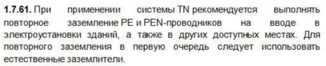
Tip #2 According to paragraphs 1, 7, 61. PUE for grounding the PE conductor at the input to the building, it is recommended to use natural ground electrodes.
Basic requirements for the separation of the PEN conductor
Everything you need to know for the competent performance of such work is spelled out in the provisions of the PUE. In particular, the need for such a connection is mentioned in clause 7.1.13

How the connection should look in the diagram is described in paragraph 1.7.135 - when at any place the REN conductor is divided into neutral and ground wires, their subsequent combination is not allowed.

After separation, tires are considered different and must be marked accordingly - zero in blue, and PE is marked in yellow-green.
The jumper between the ground bus and the zero bus is made of a material with a cross section no less than the busbars themselves from which the PE and N wires go further. In this case, the PE protective conductor bus can contact the transformer case, and the n bus is separately installed on insulators. The PE bus must be grounded - ideally, there should be a separate circuit for it (PUE - 1.7.61).

When using RCD devices, the zero used to connect electrical equipment should not come into contact with the zero that comes to the input machine and counter. According to this principle, all these devices are connected.
The place of separation of the PEN conductor into PE and N wire, for a number of reasons, is carried out in the ASU, which stands at the entrance to an apartment or private house.
The PEN wire, which will be divided into a working zero and ground, must have a cross section of at least 10 mm² if it is copper, and 16 squares if it is aluminum. Otherwise, division is prohibited.
The main types of grounding systems
Before moving on to the PEN conductor, it is worth considering in more detail the classification of existing grounding systems and their brief description.
- TN. It means a system with a solidly grounded neutral, when a common neutral from a current source is used to connect the working zero and the protective circuit (directly from the generator or transformer where the voltage is converted). A prerequisite for this system is to connect the body of any electrical appliance to a common neutral. Grounding TN has the following varieties:
- TN-C. There is a connection between the working and protective zero. An example is a three-phase network with a neutral conductor, 4 wires are used in total.
- TN-S. The system is more secure and productive, but has a higher cost. 5 wires come to the consumer: 3 phase, 1 zero and 1 protective. The distribution of potentials is carried out directly at the source of electric current.
- TN-C-S. A cheaper version of the previous protective system. The working and protective zero are supplied to the consumer in the form of a PEN conductor. At the current source, the neutrals are combined, which saves on costs.
- TT. Grounding of the consumer is carried out directly at its location. It is most often used in areas where electricity is supplied via overhead power lines. The consumer receives 3 phases and a working zero, and the ground loop is mounted nearby.
- IT. The system is characterized by the absence of zero coming to the consumer from the source. The ground loop is mounted in close proximity to the consumer. To reduce the likelihood of electric shock, all cases of electrical appliances are connected to the ground bus.
Why it is impossible to separate the PEN conductor in the floor board

This option cannot be applied for a number of reasons:
- If we take into account exclusively the provisions of the PUE, then they say that the separation of wires should take place on the introductory machine of an apartment or private separate house.
- Even if the apartment shield is considered a water machine (which is quite problematic to do), such a connection will be incorrect according to another requirement, namely, the PE conductor must be re-grounded, which cannot be achieved in a floor shield.
- Even if you contrive and bring the ground to the floor shield, then there is another obstacle that threatens with large fines. The fact is that the electrical circuit during the construction of the house is approved in several instances and its unauthorized change is a gross violation of all existing rules - in fact, this is a change in the project according to which the house was connected to the network. Such cases should be dealt with exclusively by the organization serving this house or area.
Of course, if such an organization plans any work to separate the Pen conductor, then there is no point in messing with each floor plate separately. The best option would be to divide it on an introductory machine, which will be done.

An additional argument in favor of separating the Pen conductor on one machine of a residential building is the requirement of the PUE (clause 7.1.87) to install a potential equalization system in this place.
It is forbidden to do it anywhere else, which means that the separation of the PEN conductor in the floor board will in any case be done without observing all the necessary rules and precautions. . As a result, the only correct method to make grounding in the house is a collective appeal to the organization serving the house or area
As a result, the only correct method to make grounding in the house is a collective appeal to the organization serving the house or area.
The most common mistakes when splitting a PEN conductor
When performing the separation of the PEN conductor yourself, it is necessary to strictly observe the correct sequence of this process. To achieve the most reliable contact of all connections, use high-quality electrical materials and have a reliable tool at hand that will save time.
The most common mistake is connecting the input zero to the bus, which will act as a ground. The PUE has a corresponding clause indicating that the input zero should be connected to the zero bus, and not to the protective
Therefore, after work, you should pay attention to the connection and check everything again.

As a jumper, very often they use any material that comes to hand, not paying attention to its quality. Such an error will soon lead to a fire and the need to install a new electrical panel. You should not save on such important issues as electricity in a house or apartment.
Using poor quality electrical tape can also be dangerous. For short-term loads above the nominal values, such electrical tape may melt and the contact will remain open. Which is already a violation of electrical safety and increases the chances of a short circuit. For any electrical work, it is best to use heat shrink tubing.
When working with apartment shields, a large number of twists are often encountered. This method of connection is already outdated, it gives poor-quality contact, which, like the use of aluminum with copper, can lead to a fire. Now there are special hydraulic presses that allow you to connect wires using sleeves. The cost of such products is high, but the maximum quality of the connection is achieved. In the absence of such a tool, it is best to use bolted connections with several washers.
Main earth bar PE
The PE bus or main bus is one of the components of the general grounding device of a certain object. This bus is used in electrical installations up to 1 kW. With its help, individual grounding conductors are connected, through which grounding and potential equalization are performed.
What is connected to the busPE:
- Ground conductor, which is connected to the ground electrode;
- Communication pipes made of metal;
- metal building frame;
- Parts of ventilation and air conditioning systems made of metal;
- Lightning protection system;
- Working ground conductor.
The installation of the GZSH is provided for by the rules of the PUE and is carried out inside the input switchgear or separately.
Note! If the main ground bus is located inside the device, then only the PE bus can be used in this case. .
If the tire is installed separately from the device, then the convenience of its maintenance is a prerequisite.
Separately installed ground bus, the cross section should not be less than the supply PE or PEN conductor.
It is unacceptable to use aluminum products as GZSH. The tire must be made of copper or steel.
Structurally, this bus must necessarily comply with the rules and requirements of the PUE and have the possibility of individual maintenance of conductors.
Ways to transition a multi-storey building to the TN-C-S system
It does not make sense to independently redo the TN-C system of the whole house, there are special services for this. Another question is when it will be the turn to overhaul the entire house.
Options for reworking the electrical system of a multi-storey building:
- No matter how trite, but many tenants of multi-storey buildings prefer to just wait. Now in the country, at the federal level, there are programs for capital repairs. The relevant authorities responsible for utilities can find out if the house is on the waiting list or not, and when repairs are scheduled.
- You can not wait for a major overhaul, but pay for the services of a company that installs electrical networks. Of course, this method is very costly, as the company is laying new lines, installing grounding devices, and installing new electrical panels. But in addition to electrical work, the company also takes on the regulatory framework, which it then independently certifies in all instances. Residents only need to pay for services.
- There is a collaboration option. Residents offer a lower amount, but will actively help with the work. Unfortunately, not many companies agree to this option, preferring to do everything on their own.

If none of the options listed above suit you, then you can independently separate the PEN conductor in the electrical panel in the stairwell. In this case, the expenses will be much less than when installing the introductory cabinet of the whole house. If you carry out the work yourself, but you only need to purchase consumables, the prices of which are now moderate.
Why separate the PEN conductor if a jumper is placed between the PE and N buses
A direct answer to this question is not given in the PUE and GOSTs - there are only recommendations “how to do it”, and “why” is not considered, most likely, based on the assumption that it should be clear anyway. Therefore, all subsequent explanations should be taken as the opinion of the author, supported by the principles of connecting electrical wiring and the requirements of the PUE.
The main points here are:
- In any diagram that illustrates the division of the PEN conductor into PE and N, grounding is always placed first and there is a jumper from it to the working zero. This is the main requirement that must be taken into account when separating the PEN conductor - on the contrary, it is never done under any circumstances.
- Even separately made grounding is most effective when connected through an RCD. Otherwise, even if the voltage with the body of the electrical appliance goes into the ground, there is still a risk of electric shock to a person, although much less.
- Any wire has a certain electrical resistance, respectively, the longer the wire, the higher its resistance to electric current.
To understand the "physics of the process" itself, it is necessary to consider how various connection schemes behave in the event of an emergency situation.
If there is no jumper and RCD, zero and ground are not connected
The phase enters the body of the device from it goes to the ground bus from it goes into the ground through which it goes to the transformer substation.
If we take the average value of the resistance of the grounding device as 20 ohms, the short circuit current will not be large enough to turn off the input machine. Accordingly, the electrical circuit will work until the damaged area burns out (in any case, there will be an increased temperature in this place and the wire will deteriorate sooner or later), or the damage will not develop into a full-fledged short circuit between phase and zero.
In the best case, here a person can be noticeably “tickled” with current or the device may deteriorate. At worst, the appliance may ignite and cause a fire.
If there is a jumper between zero and ground, there is no RCD
In this case, the circuit works in much the same way as if you simply put a PEN conductor into the house, with the only difference that the person will be more protected due to grounding
This will happen just because of the length of the wire - since in any case the ASU is located at some distance from the apartment or house, the resistance of the wire must be taken into account.
When the phase is closed to the device case, the leakage current will go to the ground bus, where it will have only two outputs: part of it will go to the ground, and the other will return along the neutral wire, causing the introductory apartment machine to turn off.
That is, in this case, the jumper is needed in order for the protective circuit breaker to work.
If there are jumpers between PE and N, an RCD is installed
Since the neutral and ground wires have a certain resistance to electric current, it is clear that in this case the RCD will operate normally. If a short circuit appears on the device case, the leakage current, first of all, goes through the wire to the RCD itself, and then it goes to the ASU of a residential building. Here, again, it partially goes into the ground and partially returns back through the jumper, provoking the shutdown of the introductory machine, but most likely it will not come to this, since the RCD will work earlier.
It is clear that in this case the jumper does not play a special role and is more of an extra reinsurance for that almost unbelievable case if the RCD circuit breaker does not work.
If there is no jumper between PE and N, an RCD is installed
Such a circuit will work in exactly the same way as if there was a jumper between ground and working zero. The only exception to it is the lack of insurance in case the RCD suddenly fails. Then the circuit will work according to the first option - the introductory machine may not work until the short circuit to the device case turns into a short circuit between phase and zero.
In fact, such a scenario is practically impossible, because in fact such a connection is already a TN-S or even TT grounding scheme, which provides for two-factor protection - without it, such a connection will not accept energy supervision.
Main switchboard and ASU what is it in electrics differences
At various facilities for the input and distribution of electrical energy, input distribution devices (ASU) are used. Also, these devices protect conductors and consumers from overloads in the network and short circuits.
The devices installed in the ASP account for the consumed electricity, and control of its uniform distribution is carried out. ASUs operate in electrical networks with a voltage of 200 and 380 Volts, with an alternating current frequency of 50 Hz.
ASU device:
- Housing (metal box);
- One-sided panel.
The device is assembled as follows. Mounted in a metal box, one-sided panel, various equipment is installed. This equipment includes an introductory machine, fuse-links, RCDs, difautomats or conventional circuit breakers.
Note! The connection of conductors in all ASUs and MSBs is carried out only through a deafly grounded neutral. .
ASU may consist of several sections. Assembly is carried out in a suspended or floor state. According to the standards and rules of the PUE, the ASU must withstand the breaking current (shock), reaching 20 kA. The insulation of the conductors must withstand a voltage of 100 volts.
Introductory switchgears are assembled according to the design requirements provided by the customer. Since ASUs have found wide application, they can be performed in accordance with various climatic conditions.
 In case of breakdown of the ASU, you should contact a specialist
It is worth noting that the ASU and the main switchboard will perform exactly the same functions. The main difference is that the main switchboard always comes first in any electrical circuit.
Private house or cottage
In this regard, the owners of private houses are more fortunate, at no special cost the owner of the cottage can make the grounding of the house, which we talked about in our article. And implement a modern system of safe power supply in your home.
It doesn’t matter if it’s a three-phase (four-core) input or a single-phase (two-core), PEN has come to you, you can determine it with an indicator screwdriver with a phase indicator. Further in the input shield, the neutral core is connected to the distribution terminal. Jumpers go from it to the zero bus and a separate ground terminal, and a wire is also connected to it from the external grounding circuit. The place of separation of the PEN conductor can be seen in the figure:

So that you know how to properly divide the conductor, we present the rules of the EIC chapter 1.7 (grounding and protective measures) and 7.1 (safety measures):
- Separation of the PEN conductor is carried out before the input switching device (the wire runs directly to the PE and N separation bus, from which it goes to separate terminals). In other words, the combined conductor must be divided before the counter, and not after, because. according to the rules, the introductory machine is placed in front of the electricity meter.
- The cross section of the PE wire must be the same as N.
- It is forbidden to combine the protective and neutral wires further in the circuit, beyond the splitting point.
- It is not allowed to use a common bus to disconnect N and PE conductors. Need as shown in the photo:
- It is recommended to re-ground the PEN conductor at the input.
- It is forbidden to use switching devices in the circuit of PEN and PE conductors.
Flat
The owners of apartments are not lucky in this regard, as the organization of the TN-C-S system. In the specifics of supplying old apartment buildings, the PEN wire is connected in turn, from floor to floor. And in the event of an accident, such as a burnout of the neutral wire in the floor shield, two phases come to the apartment. In this case, our system stops working and becomes dangerous.

For this reason, it is forbidden to divide the PEN wire into PE and N, because in the event of an accident, the protective conductor will be energized.
To organize a safe power supply in the apartment, you need to install in the metering panel:
- voltage relay;
- RCD or differential automata;
- organize a full-fledged grounding device in the house front garden or lay an additional PE wire to the general house ASU;
- make a potential equalization system.
We draw your attention to the fact that it is forbidden to use water pipes, heating pipes and gas pipes as protective grounding!
In the event that you still managed to make wiring with a protective conductor in the apartment, before reading our article, we strongly recommend that you do not commute it with a neutral wire and an access shield, but leave it unconnected until reconstruction of the electrical wiring and will replace the old wiring from the transformer substation in accordance with the new standards. For now, you can use the additional protection devices described above.
In new apartments with a TN-C-S grounding system, the separation of the combined conductor into zero working and zero protective is carried out in the main switchboard. Two wires already go from it separately to the floor board and to the apartments, as shown in the diagram below:

Expert answer
Requirements for protective conductors
That's all I wanted to tell you about where the PEN conductor should be divided into PE and N according to the rules of the PUE. We duplicate the answer once again so that you will surely remember: in private houses, the wire must be divided to the meter in front of the introductory switching device, and in apartments this is done in the main switchboard.
- What color is the phase and zero in electrics
- How to replace the wiring in the apartment
Security Requirements
For this reason, modern buildings use five wires (3 phases, PEN and PE) that start from the busbars located in the basement. They are laid further up to the last floor. In contrast to this scheme, in the buildings of the old construction, PE branched off only in the floor electrical panel in houses with electric stoves.
- It is forbidden to use any pipes laid in the room as a PE conductor.
- If there are several grounding devices in the room, their potentials must be combined with an additional wire.

Example of modern installation of protective conductors
The PE conductor is used where it is impossible to obtain a properly performed grounding. This is typical for all multi-storey buildings. Therefore, the safety of people in these buildings directly depends on the correct connection of the PE wire. All information on how to properly make a PE conductor is set out in section 1.7 * PUE.
The TN-C earthing system, although still in use in most apartment buildings, is outdated and is being actively replaced by more advanced TN-S or TN-C-S in terms of protection. As a result, N is used in circuit diagrams as a working zero, and the PE conductor is a protective zero that appears in the circuit after the PEN wire is separated, or taken directly from the ground loop.
Basic requirements for the separation of the PEN conductor
Everything you need to know for the competent performance of such work is spelled out in the provisions of the PUE. In particular, the need for such a connection is mentioned in clause 7.1.13

How the connection should look in the diagram is described in paragraph 1.7.135 - when at any place the REN conductor is divided into neutral and ground wires, their subsequent combination is not allowed.
After separation, tires are considered different and must be marked accordingly - zero in blue, and PE is marked in yellow-green.
The jumper between the ground bus and the zero bus is made of a material with a cross section no less than the busbars themselves from which the PE and N wires go further. In this case, the PE protective conductor bus can contact the transformer case, and the n bus is separately installed on insulators. The PE bus must be grounded - ideally, there should be a separate circuit for it (PUE - 1.7.61).
When using RCD devices, the zero used to connect electrical equipment should not come into contact with the zero that comes to the input machine and counter. According to this principle, all these devices are connected.
The place of separation of the PEN conductor into PE and N wire, for a number of reasons, is carried out in the ASU, which stands at the entrance to an apartment or private house.
The PEN wire, which will be divided into a working zero and ground, must have a cross section of at least 10 mm² if it is copper, and 16 squares if it is aluminum. Otherwise, division is prohibited.
Why it is impossible to separate the PEN conductor in the floor board

This option cannot be applied for a number of reasons:
- If we take into account exclusively the provisions of the PUE, then they say that the separation of wires should take place on the introductory machine of an apartment or private separate house.
- Even if the apartment shield is considered a water machine (which is quite problematic to do), such a connection will be incorrect according to another requirement, namely, the PE conductor must be re-grounded, which cannot be achieved in a floor shield.
- Even if you contrive and bring the ground to the floor shield, then there is another obstacle that threatens with large fines. The fact is that the electrical circuit during the construction of the house is approved in several instances and its unauthorized change is a gross violation of all existing rules - in fact, this is a change in the project according to which the house was connected to the network. Such cases should be dealt with exclusively by the organization serving this house or area.
Of course, if such an organization plans any work to separate the Pen conductor, then there is no point in messing with each floor plate separately. The best option would be to divide it on an introductory machine, which will be done.

An additional argument in favor of separating the Pen conductor on one machine of a residential building is the requirement of the PUE (clause 7.1.87) to install a potential equalization system in this place.
It is forbidden to do it anywhere else, which means that the separation of the PEN conductor in the floor board will in any case be done without observing all the necessary rules and precautions.
As a result, the only correct method to make grounding in the house is a collective appeal to the organization serving the house or area.
Why separate the PEN conductor if a jumper is placed between the PE and N buses - the "physics" of the process
A direct answer to this question is not given in the PUE and GOSTs - there are only recommendations “how to do it”, and “why” is not considered, most likely, based on the assumption that it should be clear anyway. Therefore, all subsequent explanations should be taken as the opinion of the author, supported by the principles of connecting electrical wiring and the requirements of the PUE.
The main points here are:
- In any diagram that illustrates the division of the PEN conductor into PE and N, grounding is always placed first and there is a jumper from it to the working zero. This is the main requirement that must be taken into account when separating the PEN conductor - on the contrary, it is never done under any circumstances.
- Even separately made grounding is most effective when connected through an RCD. Otherwise, even if the voltage with the body of the electrical appliance goes into the ground, there is still a risk of electric shock to a person, although much less.
- Any wire has a certain electrical resistance, respectively, the longer the wire, the higher its resistance to electric current.
To understand the "physics of the process" itself, it is necessary to consider how various connection schemes behave in the event of an emergency situation.
If there is no jumper and RCD, zero and ground are not connected
The phase enters the body of the device from it goes to the ground bus from it goes into the ground through which it goes to the transformer substation.
If we take the average value of the resistance of the grounding device as 20 ohms, the short circuit current will not be large enough to turn off the input machine. Accordingly, the electrical circuit will work until the damaged area burns out (in any case, there will be an increased temperature in this place and the wire will deteriorate sooner or later), or the damage will not develop into a full-fledged short circuit between phase and zero.
In the best case, here a person can be noticeably “tickled” with current or the device may deteriorate. At worst, the appliance may ignite and cause a fire.
If there is a jumper between zero and ground, there is no RCD
In this case, the circuit works in much the same way as if you simply put a PEN conductor into the house, with the only difference being that the person will be more protected due to grounding. This will happen just because of the length of the wire - since in any case the ASU is located at some distance from the apartment or house, the resistance of the wire must be taken into account.
When the phase is closed to the device case, the leakage current will go to the ground bus, where it will have only two outputs: part of it will go to the ground, and the other will return along the neutral wire, causing the introductory apartment machine to turn off.
That is, in this case, the jumper is needed in order for the protective circuit breaker to work.
If there are jumpers between PE and N, an RCD is installed
Since the neutral and ground wires have a certain resistance to electric current, it is clear that in this case the RCD will operate normally. If a short circuit appears on the device case, the leakage current, first of all, goes through the wire to the RCD itself, and then it goes to the ASU of a residential building. Here, again, it partially goes into the ground and partially returns back through the jumper, provoking the shutdown of the introductory machine, but most likely it will not come to this, since the RCD will work earlier.
It is clear that in this case the jumper does not play a special role and is more of an extra reinsurance for that almost unbelievable case if the RCD circuit breaker does not work.
If there is no jumper between PE and N, an RCD is installed
Such a circuit will work in exactly the same way as if there was a jumper between ground and working zero. The only exception to it is the lack of insurance in case the RCD suddenly fails. Then the circuit will work according to the first option - the introductory machine may not work until the short circuit to the device case turns into a short circuit between phase and zero.
In fact, such a scenario is practically impossible, because in fact such a connection is already a TN-S or even TT grounding scheme, which provides for two-factor protection - without it, such a connection will not accept energy supervision.
Features of the separation of the PEN conductor at the input to a private house
To prevent theft of electricity, a representative of the energy supervision may require that the PEN wire be connected directly to the meter and after it be divided into the lines of the PE conductor and the working N. In general, such a connection has the right to life, but it would still be more correct to perform the separation before counter and seal the introductory machine. In this case, the connection will be more reliable, the requirements of the EMP are met, and the inspectors receive a line protected from unauthorized access.
For more information about PE and PEN conductors in a private house, see this video:
As a result, when performing the separation of the PEN conductor, it is enough to know and apply the requirements of the Electrical Installation Code, which provide comprehensive recommendations on this issue, regardless of the place and methods of connection.
I lie ... how much in this sound for the heart of the summer resident merged, how much resonated in it.
Around the correct connection of the ASP and the choice of the grounding system, a lot of copies are constantly breaking. And it breaks rather strangely - somewhere it’s enough to make a competent shield and it will be accepted, but somewhere if you have a TT, then everything is in order, but if you want TN-C-S, yes by all the rules - welcome to hell, get your brains, the brave representatives of the energy sales have already prepared spoons and are waiting.
So I had to tinker with them, argue and thoroughly rummage through the regulations. Let's leave aside general discussions about which grounding scheme is better and how to connect what, they are on the CS blog - if you want, you will find them. I want to touch on something else - if there are disputes with power engineers about the acceptance of your ASU, most likely it will not be a conversation of specialists about technical nuances, but a stupid butting with the bureaucratic machine. And the working arguments will be the same - not as better, but as written in the rules. The trick is that the rules are on our side, the main thing is to be able to search.
Briefly about what I found:
- TN-C-S has priority. You need a good reason to use TT - an unrenovated line that does not meet safety requirements. And then TT can only be used temporarily, until a good reason is eliminated - i.e. before the reconstruction of the line.
- PEN in counter or not? Absolutely not. All PEN connections to the PE busbar must comply with the cross-sectional/electrical conductivity requirements, must be open and accessible for inspection. Closed lids with seals are excluded in principle. Incomprehensible meter terminals - only after confirming the section / material.
- Does the meter need a PEN? In my case, no. The manufacturer clearly and clearly showed that the meter needs one tap from the zero line. Exactly the withdrawal, exactly from zero.
- Sealing of the separation unit PEN. Missing point 2? Ok - still no. Energosbyt has no right to climb into it with seals.
My starting situation- a new village, a new overhead line, an empty lot (no house). The only important thing here is that the line is new and that I do not need to place the ASP indoors now.
Choice between TT and TN-C-S
PUE:1.7.57. Electrical installations with voltage up to 1 kV of residential, public and industrial buildings and outdoor installations should, as a rule, be powered from a source with a dead-earthed neutral using the TN ...
“Generally” is not a figure of speech here, but a term meaning that TN is the default choice, and to simply select TT, justification is already needed.
1.1.17. To indicate the obligatory fulfillment of the requirements of the PUE, the words “should”, “should”, “necessary” and derivatives from them are used. The words "generally" mean that the requirement is predominant, and derogation from it must be justified.
There is only one justification for choosing TT - the inability to meet the security requirements for TN.
1.7.59. Power supply of electrical installations with voltage up to 1 kV from a source with a solidly grounded neutral and with grounding of open conductive parts using a ground electrode not connected to the neutral (TT system) is allowed only in cases where electrical safety conditions in the TN system cannot be ensured ...
Let's just say, the rationale is so-so, too vague. We clarify it in another document:
ASSOCIATION "ROSELECTROMONTAZH"
TECHNICAL CIRCULAR
№ 31/2012
ON RE-EARTHING AND AUTOMATIC POWER OFF AT THE INLET OF INDIVIDUAL CONSTRUCTION OBJECTS
When choosing protection measures against indirect contact in electrical installations powered by overhead lines and overhead lines up to 1 kV, you must be guided by the following:
3. When powered from overhead lines, in accordance with the instructions of clause 1.7.59 of the seventh edition of the EMP and clause 531.2.3 of IEC 60364-5-53 (the Russian analogue of GOST R 50571-5-53 is being prepared for release), a protective system should be used grounding TT. Re-grounding parameters are selected in accordance with the instructions in paragraph 2 of this technical circular.
4. The use of the TT system is considered as a temporary (forced) measure. After the reconstruction of the overhead line and the transition to VLI in electrical installations, it is necessary to switch to the TN protective earthing system; for this, a jumper should be installed in the input device between the N and PE buses.
If we are powered by overhead lines, we use TT.
If we are powered by VLI, we must switch to TN.
Those. switching to power from VLI means fulfilling the very safety requirements necessary for choosing a TN system.
What is VL and VLI?
PUE 2.4.2.Overhead line (VL) of power transmission with voltage up to 1 kV - a device for the transmission and distribution of electricity through insulated or non-insulated wires located in the open air and attached by linear fittings to supports, insulators or brackets, to walls of buildings and to engineering structures.
An overhead power line with a voltage of up to 1 kV using self-supporting insulated wires (SIP) is designated VLI.
Self-supporting insulated wire - insulated conductors twisted into a bundle, and the carrier conductor can be either insulated or uninsulated. The mechanical load can be taken either by the carrier conductor or by all conductors of the bundle.
Those. if we have an old, non-renovated line - we should use TT and the energy sales proposals are logical. If we initially have a new line or it was reconstructed and made into a SIP, the power supply company cannot ask for any TT system, let alone demand it, there are no norms that it could refer to in such requirements. For him, as an organization that obeys papers and norms, there is only TN without alternatives.
Where should I put the PEN - into the meter or to the PEN splitter?
There are several arguments here. I'll list them in order from most important to least important as I see it.- The meter is sealed, the terminal on which the wires are connected is closed with a lid. PEN must not be connected in this way.
PUE (clause 1.7.140, establishing the requirements for connections and connections of grounding and protective conductors):
1.7.140. Connections must be accessible for inspection and testing, with the exception of joints filled with compound or sealed, as well as welded, soldered and pressed connections to heating elements in heating systems and their connections located in floors, walls, ceilings and in the ground.We connected PEN to the meter - either we don’t seal it, or we get a violation of the requirements of the PUE.
- The PUE establishes requirements for the cross section of the PEN conductor. None of the counters I met contained confirmation of the compliance of the terminals with these requirements.
PUE 1.7.126.
The smallest cross-sectional areas of protective conductors must comply with Table. 1.7.5. (i.e. 16 mm2 for aluminum in CIP, 10 mm2 for copper)
The cross-sectional areas are given for the case when the protective conductors are made of the same material as the phase conductors. The cross sections of protective conductors made of other materials must be equivalent in conductivity to those given ...PUE 7.1.45.
The choice of the cross section of conductors should be carried out in accordance with the requirements of the relevant chapters of the PUE.
Single-phase two- and three-wire lines, as well as three-phase four- and five-wire lines when supplying single-phase loads, must have a cross section of zero working (N) conductors equal to the cross section of phase conductors.
Three-phase four- and five-wire lines when supplying three-phase symmetrical loads must have a cross section of zero working (N) conductors equal to the cross section of the phase conductors, if the phase conductors have a cross section of up to 16 mm2 for copper and 25 mm2 for aluminum, and for large cross sections - at least 50 % section of phase conductors.
The cross section of PEN conductors must be at least the cross section of N conductors and not less than 10 mm2 for copper and 16 mm2 for aluminum, regardless of the cross section of the phase conductors.We see in the documentation of the meter confirmation that the cross section of its terminals is equivalent to 10 mm2 for copper - then this item is not relevant. It’s just that finding a meter with such documentation is another task :) My mercury 231 does not have such confirmation - we connect PEN to its zero terminal - we get a violation of the requirements of the PUE.
- The PUE quite clearly tells us where to connect the PEN - to the PE bus. But from the point of view of papers, there is a “grey zone” here. it is not entirely clear whether the meter terminal can be considered one of the connections of the PEN conductor, and not the point of its connection (I remind you that we are now talking about the use of pieces of paper in disputes with bureaucrats or about proving our position in court, and not about an adequate discussion of technical issues). I leave this argument "reserved".
PUE 1.7.135.
When the zero working and zero protective conductors are separated starting from any point of the electrical installation, it is not allowed to combine them beyond this point along the course of energy distribution. In the place where the pen-conductor is divided into zero protective and zero working conductors, it is necessary to provide separate clamps or busbars for conductors connected to each other. The pen-conductor of the supply line must be connected to the terminal or busbar of the neutral protective PE conductor.
What is the result.
Have you connected PEN to the meter terminals and sealed it? Got a violation 1.7.126, 1.7.140, 7.1.45 and, perhaps, 1.7.135 PUE.Formally, we do not have the right to connect PEN to a meter or anything else that can be sealed. But we are obliged to connect it to the PE bus.
Does the meter need a PEN?
It would seem that everything is already clear, but additional arguments never hurt. This argument is specialIt all depends on the documentation of a particular meter, so I will tell you about my Mercury 231 (and Mercury 230 because they have the same connection schemes).
The bottom line is that there is only one direct (not through transformers) switching on of this meter, no alternative. This scheme is given in the meter's passport. And it indicates the connection of the meter by a branch from the zero line.
For hard-nosed bureaucrats - just a branch ( GOST 2.721-74 ESKD. Conditional graphic designations in schemes. General purpose symbols, Table 6c,
Electrical communication line with branches).
Those. this meter should be connected to one neutral wire taken from the zero line. We connected PEN to the meter - either we consider that this is zero, and not PEN (and here, let me remind you, TN is mandatory and it is PEN that comes to us) or we violate the instructions for connecting the meter.
PEN division schemes
Here, unfortunately, is the “grey zone”. The following document contains recommendations, not requirements, we can only refer to it as an additional argument, and not as a main one.GOST 32395-2013 "Distribution boards for residential buildings.." contains several typical diagrams of boards. Including a diagram of a panel for a cottage for three phases (APPENDIX A (reference). Exemplary diagrams of apartment and floor panels, Figure A.6 - Diagram of an apartment metering and group panel (for a cottage) connected to an external three-phase four-wire supply network).
This diagram, recommended by GOST, shows the division of PEN to the counter. By the way - none of the shield schemes recommended in this GOST implies the separation of PEN after the counter - wherever it is, it is done before. The argument is additional due to the status of “recommendation”, but it sounds good and can reinforce the position.
So, we have very specific rules, according to which if the line is new, we must use TN-C-S and divide the PEN to the meter. A good start for a dialogue with energy sales specialists. The problem is that "dialogue" is when on an equal footing. And they have an advantage - if they slow down, then nothing to them, and we are without electricity. We must shift the scales in our favor, for which we will be helped by a few more very interesting documents.
1. Order of the Ministry of Energy of January 13, 2003 N6 "On approval of the Rules for the technical operation of consumer electrical installations"
An absolutely wonderful thing that dictates the rules for connecting electrical installations. Including a list of everything that marketers can seal. The trick is that in this list there is not only a PEN separation unit, but also an introductory machine.
2.11.18. The power supply organization must seal:
terminal blocks of current transformers;
covers of transition boxes where there are circuits to electric meters;
current circuits of settlement meters in cases where electrical measuring instruments and protection devices are connected to current transformers together with meters;
test boxes with clamps for shunting the secondary windings of current transformers and the junction of voltage circuits when the calculated meters are turned off for their replacement or verification;
lattices and doors of chambers where current transformers are installed;
lattices or doors of chambers where fuses are installed on the high and low voltage side of the voltage transformers to which the calculated meters are connected;
devices on the handles of the voltage transformer disconnector drives, to which the calculated meters are connected.
In the secondary circuits of voltage transformers to which settlement meters are connected, the installation of fuses without monitoring their integrity with an effect on the signal is not allowed.
Verified settlement meters must have the seals of the organization that performed the verification on the fastening of the casings, and the seal of the energy supply organization on the cover of the meter terminal block.
To protect electrical measuring instruments, switching devices and detachable connections of electrical circuits in metering circuits from unauthorized access, they must be marked with special signs of visual control in accordance with established requirements.
Those. consent to sealing not only the separation unit (which is heresy), but also the introductory machine (which is very important for sales) is our good will, which we can withdraw at any time and demand that the marketers eliminate violations of the order of the Ministry of Energy. As part of the order, the power supply company can mark the introductory machine, but not put a seal on it.
2. Arbitration practice for the placement of metering units, informing us that in addition to electrical requirements, there are things like antitrust laws and civil codes that prohibit distributors from imposing excessive financial costs on us related to the maintenance of our property. The property is an ASU and, specifically, a meter, which, according to clause 1.5.27 of the EMP, must be protected from external conditions and placed in a room with a temperature not lower than 0 degrees in winter. For those who like to read operating conditions in the meter's passport up to -40 degrees - the PUE is a general regulatory document, the passport is the documentation of the device that must comply with the PUE. Those. PUE is a priority. If the PUE does not match the device, the PUE does not care. If the device does not comply with the PUE, the device is redone.
True, there is a difficulty here - if it comes to arbitration practice and courts, it is more logical to use a bunch of different ones instead of one magical argument. In our case, this is:
a) grid and distribution companies are monopolists (natural monopoly), respectively, their activities are regulated by the state - including “Decree of the Government of the Russian Federation of December 27, 2004 N 861 (as amended on December 4, 2017) “On approval of the Rules for non-discriminatory access to services for transmission of electrical energy and provision of these services…”. Clause 25 of these rules contains a list of what should be indicated in the technical conditions - and there are no requirements for placing the meter on a pole (or even on the wall of the house), and this list is closed and cannot be supplemented at the request of the power supply or someone something else.
b) the presence on the market of meters that, according to their passports, can be operated outdoors, does not cancel clause 1.5.27 of the PUE.
c) the presence of meters on the market from the previous paragraph does not mean that the consumer has the financial ability to purchase them to the detriment of those that are more accessible to him. In addition, the need for insulation and heating of the shield in winter imposes additional costs on the consumer, which he can avoid by placing the meter in the house. And since sales companies are monopolists, there is Article 10 of the 135-FZ “Prohibition on Abuse of a Dominant Position by an Economic Entity” for them, or rather part 3 of the first paragraph of this article, which expressly prohibits them from imposing unfavorable connection conditions on us.
d) Article 210 of the Civil Code itself, which imposes on the owner the burden of maintaining his property. The removal of the counter with a shield on the pole deprives the owner of the opportunity to ensure the safety of his property.
e) transferring the shield with the meter to the pole transfers it from a room without increased danger to conditions equivalent to a particularly dangerous room (EIC, clause 1.1.13), which creates an increased risk of electric shock and imposes additional obligations (and additional costs) on the owner of the shield ) for security.
Total- if we have a heated house in which a meter can be placed at no additional cost, the requirement to take it to an external metering board, insulated and heated in accordance with the requirements of clause 1.5.27 imposes on us, as consumers, additional costs, responsibility, creates an increased danger to surrounding and, at the same time, contradicts the Rules of non-discriminatory access, approved by Decree of the Government of the Russian Federation of December 27, 2004 N 861.
PUE 1.5.27.
Meters should be placed in dry rooms easily accessible for maintenance, in a place that is sufficiently free and not cramped for work with a temperature not lower than 0 ° C in winter.
Meters of general industrial design are not allowed to be installed in rooms where, due to production conditions, the temperature can often exceed +40 ° C, as well as in rooms with aggressive environments.
It is allowed to place meters in unheated rooms and corridors of switchgears of power plants and substations, as well as in outdoor cabinets. At the same time, their stationary winter insulation should be provided for by means of insulating cabinets, hoods with heating of the air inside them with an electric lamp or a heating element to ensure a positive temperature inside the hood, but not higher than + 20 ° С.
Decree of the Government of the Russian Federation of December 27, 2004 N 861 “On approval of the Rules for non-discriminatory access to services for the transmission of electrical energy ...”
25(1). The technical conditions for applicants provided for in paragraphs 12.1 and 14 of these Rules must indicate:
a) connection points that cannot be located further than 25 meters from the border of the site on which the applicant's connected objects are (will be) located;
a(1)) maximum power in accordance with the application and its distribution for each point of connection to the power grid facilities;
b) justified requirements for strengthening the existing electrical network in connection with the connection of new capacities (construction of new power lines, substations, increase in the cross-section of wires and cables, replacement or increase in the power of transformers, expansion of switchgear, modernization of equipment, reconstruction of electric grid facilities, installation of control devices voltages to ensure the reliability and quality of electric energy), mandatory for execution by the grid organization at its expense;
c) requirements for electrical energy (power) metering devices, relay protection devices and devices that provide control of the maximum power value;
d) distribution of responsibilities between the parties for the fulfillment of technical specifications (measures for technological connection within the boundaries of the site where the applicant's power receiving devices are located are carried out by the applicant, and technological connection measures up to the border of the site where the applicant's power receiving devices are located, including the settlement of relations with by other persons, carried out by the network organization).
25(2). In the case of technological connection of power receiving devices owned by citizens individually engaged in horticulture, horticulture or dacha farming on the territory of a horticultural, horticultural or dacha non-profit association, the grid organization, when developing technical specifications, should provide for the possibility of introducing a restriction on the applicant's consumption regime in cases provided for by the legislation of the Russian Federation while ensuring the supply of electrical energy to other consumers without limiting the mode of their consumption.
135-FZ (On protection of competition)
Article 1, paragraph 3
Actions (inaction) of an economic entity occupying a dominant position, which result or may result in the prevention, restriction, elimination of competition and (or) infringement of the interests of other persons (economic entities) in the field of entrepreneurial activity or an indefinite number of consumers, are prohibited, including the following actions ( inaction):
…
3) imposing on the counterparty the terms of the contract that are unfavorable for him or not related to the subject of the contract (economically or technologically unjustified and (or) not directly provided for by federal laws, regulatory legal acts of the President of the Russian Federation, regulatory legal acts of the Government of the Russian Federation, regulatory legal acts of authorized federal executive bodies or judicial acts of the requirement to transfer financial resources, other property, including property rights, as well as consent to conclude an agreement, subject to the introduction of provisions regarding the goods in which the counterparty is not interested, and other requirements);
Civil Code of the Russian Federation (Part One)" dated November 30, 1994 N 51-FZ
Article 210. Burden of maintenance of property
The owner bears the burden of maintaining the property belonging to him, unless otherwise provided by the "law" or the contract.
Those. consent to place the ASU in a shield on a pole, and not in the house, this is our good will, which we can again withdraw (although there are some difficulties if the house was already built at the time the ASU was put on a pole).
Practice examples
The most common pole-mounted meter case, which has well addressed the issue of imposing excess costs on the user compared to placing the meter in the house. True, it dates back to the time when disputes between networks and users were resolved by the FAS and saw them as a violation of competition. Now we have to make more efforts to convince the court - Decision of the Fifteenth Arbitration Court of Appeal dated 10/27/2010 n 15AP-10325/2010 in case n A53-10201/2010 In the case of invalidating decisions and orders by which the company was found to have violated Part 1 of Art. 10 of the Federal Law “On Protection of Competition”, and the obligation to eliminate these violations. Court of First Instance Arbitration Court of the Rostov Region
Decision of the Talmensky District Court No. 2-570/2016 2-570/2016~M-456/2016 570/2016 M-456/2016 dated October 17, 2016 in case No. 2-570/2016- if we already had a meter in the house but its service life has expired, we have the right to install a new one in the same way in the house. Demanding to take him outside is illegal.
Decision of the Kalininsky District Court in case 2-1393/2014 ~ M-1115/2014- if it is not the networks that insist on taking the meters to the poles, but the SNT board, threatening to turn off the electricity, this is also illegal.
And something less optimistic. Decision of the Krasnoglinsky District Court of Samara No. 2-157/2015 2-157/2015 (2-2852/2014;)~M-2781/2014 2-2852/2014 M-2781/2014 dated February 18, 2015 in the case No. 2-157/2015- if the networks decide to put their counter on the pole, they can do so. The bad thing is that we don’t know how they connect such meters and whether the PEN connections are reliable there or it’s already N, and this decision shows that the plaintiff did not pay the attention of the court to these issues, did not conduct an examination, and as a result, the court accepted side of networks.
3. Legal status of the PUE. PUE is a regulatory document that is mandatory for citizens and organizations. Violation of the PUE is a violation of Article 9.11 of the Code of Administrative Offenses of the Russian Federation and the administrative responsibility of the executive.
Article 9.11.
Violation of the rules for the use of fuel, electrical and thermal energy, the rules for the construction of electrical installations, the operation of electrical installations, fuel and energy-consuming installations, heating networks, storage facilities, maintenance, sale and transportation of energy carriers, fuel and products of its processing - entails the imposition of an administrative fine on citizens in the amount of from one thousand to two thousand rubles; on officials - from two thousand to four thousand roubles; for persons engaged in entrepreneurial activities without forming a legal entity - from two thousand to four thousand rubles or an administrative suspension of activities for a period of up to ninety days; on legal entities - from twenty thousand to forty thousand rubles or an administrative suspension of activities for a period of up to ninety days.
When an energy retailer enters PEN into a meter, a specific executive of the energy retailer signs an administrative offense. When the power supply does not accept the ASU until the PEN is in the meter, a specific executive person signs under violation of the terms of the contract with the consumer (violation of the terms and conditions of technological connection).
Conclusions:
If the line is old - choose TT.If the line is new or reconstructed, but the power supply company offers TT, it violates the requirements clause 1.7.57 of the EIC and requirements technical circular No. 31/2012 of the ROSELECTROMONTAZH association.
If the power supply company offers to put PEN into the meter, it violates the requirements 1.7.126, 1.7.140, 7.1.45 and, perhaps, 1.7.135 PUE. Most likely, this also violates instructions for connecting the meter(depending on the connection scheme indicated in his passport), which leads to a loss of warranty and raises the question of the legality of using such a meter to measure electricity consumption.
Moreover, by dividing the PEN to the counter, we follow the recommendations GOST 32395-2013, and when connecting the meter with a zero tap (as in my case with 231m mercury), we follow the requirements of the meter manufacturer.
- For TN-C-S Mandatory Statement we refer to paragraphs 1.7.57 and 1.7.59 of the PUE and paragraph 4 of the technical circular of the association "ROSELECTROMONTAZH" No. 31/2012
- For the statement that PEN cannot be entered into the counter we refer to paragraphs 1.7.126, 1.7.140, 7.1.45 and 1.7.135 of the PUE, the meter passport (if it is indicated in it), GOST 32395-2013 “Distribution boards for residential buildings ..” (Figure A.6) .
- To assert that the PEN node does not require and should not be sealed we refer to clause 2.11.18 of the Order of the Ministry of Energy dated 13.01.2003 N6 “On Approval of the Rules for the Technical Operation of Consumer Electrical Installations”
- If you have to argue seriously, we recall the requirements of the same paragraph 2.11.18 regarding the introductory machine (or rather their absence) and administrative responsibility of officials for violation of the EMP.
- If the networks are trying to add to the technical conditions an indication of an inconvenient point for us to place a shield with a counter we use clause 25 of Decree of the Government of the Russian Federation of December 27, 2004 N 861 “On Approval of the Rules for Non-Discriminatory Access to Electricity Transmission Services ...”, which establishes a closed list of what may be in the technical specifications and demand that all unnecessary be removed.
- If the matter went to court, we start with the fact that networks are monopolists and are required to act in accordance with paragraph 3 of Article 1 of 135-FZ (On Protection of Competition), i.e. cannot impose unfavorable terms of the contract on us. And then we indicate the entire set of arguments, from the points of the EMP that are violated by their requirements, to the additional costs that the requirements of the networks impose on us.
And we can demand literal compliance with the rules for connecting subscribers, which puts the networks in an unpleasant situation, because. they cannot formally refuse this, violate the deadlines without consequences, too, and compliance with the rules means abandoning the meter on the pole, extra seals and other things loved by the energy sales. Antimonopoly legislation, the Civil Code of the Russian Federation, arbitration practice and administrative liability of specific network executives for violations add weight to our requirements.
My story is a little simpler - until the house is built, it makes no sense for me to fight to transfer the shield to it. TN-C-S is, even with a plastic box on top of the separation node, and that's enough.
The shield itself turned out to be very simple, although it was assembled urgently and from what was in the nearest store. I also did not have time to drill the case for PG, alas ((
Phases from SIP go to the machine, PEN to the PE bus. The PE bus is connected by a jumper to the N bus. Zero from the N bus to the counter. The phases from the meter first went to the second machine, now it has been replaced by terminals. The PE terminal is still working as grounding of the shield body.

The PE and N busbars are made with simple, but pleasant to use TDM distribution blocks, which fit into a box for 4 machines. It turned out a compromise - the networks received a seal of the meter, the introductory machine and the PEN separation unit, I received the PEN unit, in which at any time you can stretch connections, connect an input or a temporary outlet.
P.S. Thoughts on why it is so.
My communication with MOESK engineers began rather strangely - with persistent recommendations to put PEN into the meter and not even think about selectivity and other interesting things.
I wrote a request about the implementation of TN-C-S and received such a strange answer. I rummaged through the net, typed in arguments and wrote another request ... and again I got about the same answer. I thoroughly rummaged through the regulations, wrote, clarified, additionally requested ... and in the end it turned out that not robots were sitting at the other end, but quite sane people who read my arguments, considered, rechecked and agreed with them. Later it turned out that I was almost the first subscriber who wanted TN-C-S. In parallel with this, there was communication with a hired electrician, who made a shield nearby and helped with connecting the wires on the pole. And in his practice, I was one of the few who wanted something more than TT.
And somehow both this and that communication ended at the same time and the puzzle took shape - most of the people who make the connection for the dacha have no idea about the existence of TN-C-S. The electricians they hire default to a TT configuration that the networks will accept without question, and don't even talk about the existence of anything else to get the job done quickly and get the money. And network engineers, who, in theory, should make sure that new connections are made by the correct TN-C-S with good re-grounding, act as they were “taught by their ancestors”, as is customary and convenient for energy sales, which require them to understand, and not modern and correct. And it turns out a vicious circle - customers do not know about the new - performers are afraid to tell them something so as not to complicate their lives - and networks stimulate this behavior without question, accepting outdated connections and resisting the new. Although, to the credit of the MOESK engineer with whom I spoke, the dialogue with him was, albeit difficult, but productive, and the plug is somewhere deeper, where not engineers, but accountants sit, counting stolen kilowatts.