The ability of concrete to withstand mechanical and thermal stress is called strength. This is the most important characteristic that affects operating parameters designs.
All rules relating to testing concrete for tension, compression and bending are prescribed in GOST 18105-86. An important characteristic The reliability of the material is the coefficient of variation, which characterizes the homogeneity of the mixture (Vm).

where S m- quadratic deviation of strength, R m is the strength of the concrete in the batch.
According to GOST 10180-67, the cubic compressive strength of the material is determined. It is calculated by compressing control cube samples with stiffeners at the age of 28 days. For class B25 and above, the prismatic index should be 0.75, for compositions with a class below B25 - 0.8.
Requirements for design strength, in addition to GOSTs, are also spelled out in SNiPs. For example, the stripping index of unloaded horizontal structures with a span of less than 6 meters should be at least 70% of the design strength, if the span length exceeds 6 meters - 80%.
Sample testing makes it possible to determine the quality of the mixture, but not the characteristics of the concrete in the structure. Such studies are carried out in accordance with GOST 18105-2010 and use the following methods:
- destructive,
- indirect destructive,
- direct destructive.
Direct methods of non-destructive testing enjoy considerable popularity. The main methods of this type include ultrasonic or mechanical.
Concrete strength control methods according to GOST22690-88
- separation;
- separation with chipping;
- rib chipping.
Tools needed for research
- the electronic unit;
- device for tearing off with a device for gluing to concrete;
- sensors;
- dowels and anchors;
- standard metal rod.

The graph reflects the strength gain of the material over time, while line A is vacuum processing, B is natural hardening, C is the change in the index after vacuum processing.
Testing the strength of concrete by pull-off method
The basis of this type of study is the measurement of the maximum force to tear off a part concrete structure. Moreover, the breaking load must be applied to flat surface by gluing the device disk. Used for gluing adhesive compositions epoxy based. GOST22690-88 specifies adhesives ED16 and ED20 with cement filler. You can also use two-component formulations. The separation area is determined after each test. After pull-off and force calculation, the concrete tensile strength (Rbt) is measured. Using the empirical dependence and this indicator, you can calculate the indicator R - compressive strength. To do this, use the formula:
Rbt = 0.5∛ (R^2)
Breakaway with chipping
After the concrete has hardened, an anchor device is placed in a pre-drilled hole, after which it is pulled out with a part of the concrete. This method is very similar to the one described earlier. The main difference is the way the tool is attached to the surface. The tearing force is generated by flap anchors. The anchor is placed in the hole and measured P - breaking force. GOST 22690 indicates the transition of strength concrete composition for compression according to the formula:
R = m1 * m2 *P,
where m2 is the coefficient of compressive strength transition, depending on the conditions of hardening and the type of concrete, m1 is the coefficient reflecting the maximum parameters of large aggregate (loose stone materials).
Restrictions for use this method research is dense reinforcement and a slight thickness of the structure. The surface thickness must be more than twice the length of the anchor.
Rib chipping method
The strength of concrete with this method is determined by the force (P) required to chip off a part of the structure placed on the edge outside. The device is mounted on the surface using an anchor bolt with a dowel. The following formula is used to determine the indicator:
R = 0.058 * m * (30P + P2),
where m is a coefficient reflecting the fineness of the aggregate.
Ultrasonic method
The action of ultrasonic testing devices is based on the relationship between the speed with which waves propagate through the structure and its strength. Based this method it is determined that the speed, as well as the propagation time of the waves, correspond to the strength of concrete.

For prefabricated linear structures, the through-transmission method is used. In this case, ultrasonic transducers are located with opposite sides designs. Flat, hollow-core and ribbed floor slabs, as well as Wall panels are examined by surface transillumination, in which a wave transducer (flaw detector) is placed on one side of the structure.
To ensure maximum acoustic contact with the working surface, viscous contact materials (for example, grease) are chosen. A dry version is possible with the use of protectors and cone nozzles. Installation of ultrasonic devices is carried out at a distance of at least 3 cm from the edge.

Tests are carried out in accordance with GOST22690.2-77. Determination of the strength of concrete is carried out within 5-50 MPa. An impact is applied to a flat test surface, resulting in two indentations: on the reference metal rod and on the surface of the base. With each blow, the rod is moved 10 mm into the hole in the hammer body. The base is struck through white carbon paper. An angular scale is used to measure prints on paper.
For studies based on elastic rebound, a Schmidt hammer, pistols from Borovoy, TsNIISK, and a KM sclerometer with a rod striker are used. The cocking and start-up of the striker occur automatically at the moment the striker touches the tested base. The rebound value of the striker is fixed by a special pointer on the scale of the apparatus.
Put into effect by order of the Federal Agency for Technical Regulation and Metrology dated September 25, 2015 N 1378-st
Interstate standard GOST 22690-2015
"CONCRETE. DETERMINATION OF STRENGTH BY MECHANICAL METHODS OF NON-DESTRUCTIVE TESTING"
Concretes. Determination of strength by mechanical methods of nondestructive testing
Instead of GOST 22690-88
Foreword
The goals, basic principles and basic procedure for carrying out work on interstate standardization are established by GOST 1.0-92 "Interstate standardization system. Basic provisions" and GOST 1.2-2009 "Interstate standardization system. Interstate standards, rules and recommendations for interstate standardization. Rules for the development, adoption, application, renewal and cancellation
About the standard
1 Developed by the Structural Subdivision of JSC "NIC "Construction" Research, Design and Technological Institute of Concrete and Reinforced Concrete named after A.A. Gvozdev (NIIZhB)
2 Introduced by the Technical Committee for Standardization TC 465 "Construction"
3 Adopted by the Interstate Council for Standardization, Metrology and Certification (Minutes of June 18, 2015 N 47)
|
Short name of the country according to MK (ISO 3166) 004-97 |
Country code according to MK (ISO 3166) 004-97 |
Abbreviated name of the national standards body |
|
Ministry of Economy of the Republic of Armenia |
||
|
Belarus |
State Standard of the Republic of Belarus |
|
|
Kazakhstan |
State Standard of the Republic of Kazakhstan |
|
|
Kyrgyzstan |
Kyrgyzstandart |
|
|
Moldova-Standard |
||
|
Rosstandart |
||
|
Tajikistan |
Tajikstandart |
4 By order of the Federal Agency for Technical Regulation and Metrology dated September 25, 2015 N 1378-st, the interstate standard GOST 22690-2015 was put into effect as a national standard Russian Federation since April 1, 2016
5 This standard takes into account the main regulatory provisions regarding the requirements for mechanical methods for non-destructive testing of the strength of concrete of the following European regional standards:
EN 12504-2:2001 Testing concrete in structures - Part 2: Non-destructive testing - Determination of rebound number
EN 12504-3:2005 Testing concrete in structures - Determination of pull-out force.
Degree of conformity - non-equivalent (NEQ)
6 Instead of GOST 22690-88
1 area of use
This standard applies to structural heavy, fine-grained, light and tension concrete of monolithic, prefabricated and precast-monolithic concrete and reinforced concrete products, structures and structures (hereinafter referred to as structures) and establishes mechanical methods for determining the compressive strength of concrete in structures by elastic rebound, shock impulse, plastic deformation, separation, chipping of the rib and separation with chipping.
2 Normative references
This standard uses normative references to the following interstate standards:
GOST 166-89 (ISO 3599-76) Calipers. Specifications
GOST 577-68 Dial gauges with division value 0.01 mm. Specifications
GOST 2789-73 Surface roughness. Parameters and characteristics
GOST 10180-2012 Concrete. Methods for determining the strength of control samples
GOST 18105-2010 Concrete. Strength control and assessment rules
GOST 28243-96 Pyrometers. General technical requirements
GOST 28570-90 Concrete. Methods for determining strength from samples taken from structures
GOST 31914-2012 High-strength heavy and fine-grained concretes for monolithic structures. Rules for quality control and assessment
Note - When using this standard, it is advisable to check the validity of reference standards in the information system common use- on the official website of the Federal Agency for Technical Regulation and Metrology on the Internet or according to the annual information index "National Standards", which was published as of January 1 of the current year, and according to the issues of the monthly information index "National Standards" for the current year. If the reference standard is replaced (modified), then when using this standard, you should be guided by the replacing (modified) standard. If the referenced standard is canceled without replacement, the provision in which the reference to it is given applies to the extent that this reference is not affected.
3 Terms and definitions
This standard uses the terms according to GOST 18105, as well as the following terms with their respective definitions;
3.2 non-destructive mechanical methods for determining the strength of concrete: Determination of the strength of concrete directly in the structure under local mechanical action on concrete (impact, separation, chipping, indentation, separation with chipping, elastic rebound).
3.3 indirect non-destructive methods for determining the strength of concrete: Determination of the strength of concrete according to pre-established calibration dependencies.
3.4 direct (standard) non-destructive methods for determining the strength of concrete: Methods that provide for standard test schemes (tearing with shearing and shearing of the rib) and allowing the use of known calibration dependencies without reference and adjustment.
3.5 calibration dependence: Graphical or analytical dependence between the indirect strength characteristic and the compressive strength of concrete, determined by one of the destructive or direct non-destructive methods.
3.6 indirect strength characteristics (indirect indicator): The magnitude of the applied force during local destruction of concrete, the magnitude of the rebound, the impact energy, the size of the imprint or other indication of the device when measuring the strength of concrete by non-destructive mechanical methods.
4 General provisions
4.1 Non-destructive mechanical methods are used to determine the compressive strength of concrete at the intermediate and design age established by the design documentation and at an age exceeding the design age when examining structures.
4.2 Non-destructive mechanical methods for determining the strength of concrete, established by this standard, are divided by type mechanical impact or a defined indirect characteristic on the method:
Elastic rebound;
plastic deformation;
shock impulse;
Breakaway with chipping;
Rib chipping.
4.3 Non-destructive mechanical methods for determining the strength of concrete are based on the relationship between the strength of concrete and indirect strength characteristics:
The method of elastic rebound on the relationship between the strength of concrete and the value of the rebound of the striker from the surface of the concrete (or the striker pressed against it);
The method of plastic deformation in relation to the strength of concrete with the dimensions of the imprint on the concrete of the structure (diameter, depth, etc.) or the ratio of the diameter of the imprint on concrete and a standard metal sample when the indenter is struck or the indenter is pressed into the concrete surface;
Impact impulse method on the relationship between the strength of concrete and the energy of impact and its changes at the moment of impact of the striker with the concrete surface;
The method of tearing off the tension bond required for local destruction of concrete when a metal disk glued to it is torn off, equal to the tearing force divided by the projection area of the concrete tearing surface onto the plane of the disk;
The method of detachment with chipping on the connection of the strength of concrete with the value of the force of local destruction of concrete when the anchor device is pulled out of it;
Rib shearing method on the relationship of concrete strength with the value of the force required to shear a section of concrete on a structure edge.
4.4 In general, non-destructive mechanical methods for determining the strength of concrete are indirect non-destructive methods for determining strength. The strength of concrete in structures is determined by experimentally established calibration dependencies.
4.5 The tear-off method with shearing during testing in accordance with the standard scheme in Appendix A and the method of shearing off the rib during testing in accordance with the standard scheme in Appendix B are direct non-destructive methods for determining the strength of concrete. For direct non-destructive methods, it is allowed to use the calibration dependencies established in Annexes C and D.
NOTE Standard test schemes are applicable to a limited range of concrete strengths (see Annexes A and B). For cases not related to standard test schemes, calibration dependencies should be established according to general rules.
4.6 The test method should be selected taking into account the data given in Table 1 and additional restrictions, established by manufacturers specific measuring instruments. The use of methods outside the concrete strength ranges recommended in Table 1 is allowed with scientific and technical justification based on the results of studies using measuring instruments that have passed metrological certification for an extended concrete strength range.
Table 1
4.7 Determination of the strength of heavy concrete of design classes B60 and higher or with an average compressive strength of concrete R m ≥ 70 MPa in monolithic structures must be carried out taking into account the provisions of GOST 31914.
4.8 The strength of concrete is determined in sections of structures that do not have visible damage (peeling of the protective layer, cracks, cavities, etc.).
4.9 The age of concrete of controlled structures and its sections should not differ from the age of concrete of structures (sections, samples) tested to establish a calibration dependence by more than 25%. The exceptions are the control of strength and the construction of a calibration dependence for concrete whose age exceeds two months. In this case, the age difference individual structures(plots, samples) is not regulated.
4.10 Tests are carried out at a positive temperature of concrete. It is allowed to test at negative temperature concrete, but not lower than minus 10°C, when establishing or linking the calibration dependence, taking into account the requirements of 6.2.4. The temperature of the concrete during testing must correspond to the temperature provided for by the operating conditions of the devices.
Calibration dependencies established at a concrete temperature below 0°C are not allowed to be used at positive temperatures.
4.11 If it is necessary to test concrete structures after heat treatment at a surface temperature T≥40°C (to control the tempering, transfer and stripping strength of concrete), the calibration dependence is established after determining the strength of concrete in the structure indirectly non-destructive method at a temperature of t = (T ± 10) ° C, and testing of concrete by a direct non-destructive method or testing of samples - after cooling at normal temperature.
5 Measuring instruments, equipment and tools
5.1 Measuring instruments and devices for mechanical testing, designed to determine the strength of concrete, must be certified and verified in in due course and must comply with the requirements of Appendix D.
5.2 Readings of instruments calibrated in units of concrete strength should be considered as an indirect indicator of concrete strength. These devices should be used only after establishing the calibration dependence "instrument reading - concrete strength" or linking the dependence set in the device in accordance with 6.1.9.
5.3 A tool for measuring the diameter of indentations (caliper according to GOST 166) used for the plastic deformation method must provide measurement with an error of not more than 0.1 mm, a tool for measuring the depth of an indentation (caliper type according to GOST 577, etc.) - with an error no more than 0.01 mm.
5.4 Standard schemes for testing the method of separation with shearing and spalling of the rib provide for the use of anchor devices and grips in accordance with Annexes A and B.
5.5 For the pull-off method, anchor devices should be used, the insertion depth of which should not be less than the maximum size of the coarse concrete aggregate of the structure being tested.
5.6 For the tear-off method, use steel discs with a diameter of at least 40 mm, a thickness of at least 6 mm and at least 0.1 diameter, with the roughness parameters of the glued surface being at least Ra = 20 µm according to GOST 2789. concrete.
6 Test preparation
6.1 Procedure for preparing for testing
6.1.1 Preparation for testing includes checking the instruments used in accordance with the instructions for their operation and establishing calibration dependencies between the concrete strength and the indirect strength characteristic.
6.1.2 The calibration dependence is established on the basis of the following data:
The results of parallel tests of the same sections of structures by one of the indirect methods and the direct non-destructive method for determining the strength of concrete;
Results of testing sections of structures by one of the indirect non-destructive methods for determining the strength of concrete and testing core samples taken from the same sections of the structure and tested in accordance with GOST 28570;
The results of testing standard concrete samples by one of the indirect non-destructive methods for determining the strength of concrete and mechanical tests in accordance with GOST 10180.
6.1.3 For indirect non-destructive methods for determining the strength of concrete, the calibration dependence is established for each type of normalized strength specified in 4.1 for concretes of the same nominal composition.
It is allowed to build one calibration dependence for concrete of the same type with one type of coarse aggregate, with a single production technology, differing in nominal composition and normalized strength value, subject to the requirements of 6.1.7
6.1.4 The permissible difference in the age of concrete of individual structures (sections, samples) when establishing a calibration dependence on the age of concrete of a controlled structure is taken according to 4.9.
6.1.5 For direct non-destructive methods according to 4.5, it is allowed to use the dependencies given in Appendices C and D for all types of normalized concrete strength.
6.1.6 The calibration dependence must have a standard (residual) deviation S T . H. M , not exceeding 15% of the average concrete strength of the sections or samples used in the construction of the dependence, and the correlation coefficient (index) is not less than 0.7.
It is recommended to use a linear relationship of the form R = a + b K (where R is the strength of concrete, K is an indirect indicator). The methodology for establishing, estimating parameters and determining the conditions for applying a linear calibration dependence is given in Appendix E.
6.1.7 When constructing a calibration dependence, the deviations of individual values of concrete strength R i f from the average value of the concrete strength of sections or samples R̅ f used to construct the calibration dependence must be within:
From 0.5 to 1.5 average concrete strength R̅ f at R̅ f ≤ 20 MPa;
From 0.6 to 1.4 average concrete strength R̅ f at 20 MPa< R̅ ф ≤ 50 МПа;
From 0.7 to 1.3 average concrete strength R̅ f at 50 MPa< R̅ ф ≤ 80 МПа;
From 0.8 to 1.2 average concrete strength R̅ f at R̅ f > 80 MPa.
6.1.8 Correction of the established dependence for concretes of intermediate and design age should be carried out at least once a month, taking into account additionally obtained test results. The number of samples or areas of additional tests during the adjustment should be at least three. The correction method is given in Appendix E.
6.1.9 It is allowed to use indirect non-destructive methods for determining the strength of concrete, using calibration dependencies established for concrete that differs from the tested one in composition, age, hardening conditions, humidity, with reference in accordance with the methodology in Appendix G.
6.1.10 Without reference to specific conditions according to Appendix G, the calibration dependences established for concrete that differs from the tested one can only be used to obtain approximate strength values. It is not allowed to use approximate strength values without reference to specific conditions to assess the strength class of concrete.
6.2 Construction of a calibration dependence based on the results of testing the strength of concrete in structures
6.2.1 When constructing a calibration dependence based on the results of testing the strength of concrete in structures, the dependence is established by single values of the indirect indicator and concrete strength of the same sections of structures.
For a single value of the indirect indicator, the average value of the indirect indicator in the area is taken. For a single value of the strength of concrete, the strength of the concrete of the site, determined by a direct non-destructive method or testing of selected samples, is taken.
6.2.2 Minimum number unit values for constructing a calibration dependence based on the results of testing the strength of concrete in structures - 12.
6.2.3 When constructing a calibration dependence based on the results of testing the strength of concrete in structures not subject to testing, structures or their zones, preliminary measurements are carried out by an indirect non-destructive method in accordance with the requirements of Section 7.
Then the sites are selected in the number provided for in 6.2.2, on which the maximum, minimum and intermediate values of the indirect indicator are obtained.
After testing by an indirect non-destructive method, the sections are tested by a direct non-destructive method or samples are taken for testing in accordance with GOST 28570.
6.2.4 To determine the strength at a negative temperature of concrete, the sections selected for building or linking the calibration dependence are first tested by an indirect non-destructive method, and then samples are taken for subsequent testing at a positive temperature or heated external sources heat (infrared emitters, heat guns etc.) to a depth of 50 mm to a temperature not lower than 0°C and tested by a direct non-destructive method. The temperature control of the heated concrete is carried out at the depth of installation of the anchor device in the prepared hole or along the surface of the chip in a non-contact way using a pyrometer according to GOST 28243.
Rejection of the test results used to build the calibration dependence at a negative temperature is allowed only if the deviations are associated with a violation of the test procedure. In this case, the rejected result should be replaced by the results of a repeated test in the same area of the structure.
6.3 Construction of a calibration dependence on control samples
6.3.1 When constructing a calibration dependence on control samples, the dependence is established by single values of the indirect indicator and concrete strength of standard cube samples.
For a single value of the indirect indicator, the average value of the indirect indicators for a series of samples or for one sample (if the calibration dependence is established for individual samples) is taken. For a single value of the strength of concrete, the strength of concrete in a series according to GOST 10180 or one sample (calibration dependence for individual samples) is taken. Mechanical Tests samples according to GOST 10180 are carried out immediately after testing by an indirect non-destructive method.
6.3.2 When constructing a calibration dependence based on the results of testing sample cubes, at least 15 series of sample cubes according to GOST 10180 or at least 30 individual sample cubes are used. Samples are made in accordance with the requirements of GOST 10180 in different shifts, for at least 3 days from concrete of the same nominal composition, according to the same technology, with the same hardening mode as the structure to be controlled.
The unit values of the concrete strength of the sample cubes used to build the calibration dependence must correspond to the deviations expected in production, while being within the ranges established in 6.1.7.
6.3.3 The calibration dependence for the methods of elastic rebound, shock impulse, plastic deformation, separation and chipping of the rib is established on the basis of the results of testing the manufactured sample cubes, first by the non-destructive method, and then by the destructive method in accordance with GOST 10180.
When establishing a calibration dependence for the tear-off method with shearing, the main and control samples are made according to 6.3.4. An indirect characteristic is determined on the main samples, control samples are tested in accordance with GOST 10180. The main and control samples must be made from the same concrete and harden under the same conditions.
6.3.4 The dimensions of the samples should be selected in accordance with the largest aggregate size in concrete mix according to GOST 10180, but not less than:
100 x 100 x 100 mm for the methods of rebound, shock impulse, plastic deformation, as well as for the method of separation with chipping (control samples);
200 x 200 x 200 mm for the method of chipping the rib of the structure;
300 x 300 x 300 mm, but with a rib size of at least six anchor device installation depths for the pull-out method with shearing (basic samples).
6.3.5 To determine the indirect strength characteristics, tests are carried out in accordance with the requirements of Section 7 on the side (in the direction of concreting) faces of the sample cubes.
The total number of measurements on each sample for the method of elastic rebound, shock impulse, plastic deformation upon impact must be at least the established number of tests in the area according to Table 2, and the distance between the impact points must be at least 30 mm (15 mm for the shock impulse method). For the indentation plastic deformation method, the number of tests on each face must be at least two, and the distance between the test points must be at least two indent diameters.
When establishing a calibration dependence for the rib shearing method, one test is carried out on each side rib.
When establishing the calibration dependence for the method of separation with shearing, one test is carried out on each side face of the main sample.
6.3.6 When tested by the method of elastic rebound, shock impulse, plastic deformation upon impact, the specimens shall be clamped in a press with a force of not less than (30 ± 5) kN and not more than 10% of the expected value of the breaking load.
6.3.7 The samples tested by the pull-off method are installed on the press so that the surfaces on which the pull-out was carried out do not adjoin the press base plates. The test results according to GOST 10180 are increased by 5%.
7 Testing
7.1 General requirements
7.1.1 The number and location of controlled sections in structures must comply with the requirements of GOST 18105 and be indicated in the design documentation for structures or be set taking into account:
Control tasks (determining the actual class of concrete, stripping or tempering strength, identifying areas of reduced strength, etc.);
Type of construction (columns, beams, slabs, etc.);
Placement of grips and order of concreting;
Structural reinforcement.
The rules for assigning the number of test sites for monolithic and prefabricated structures in the control of concrete strength are given in Appendix I. When determining the strength of concrete of the examined structures, the number and location of the sections should be taken according to the survey program.
7.1.2 Tests are carried out on a section of the structure with an area of 100 to 900 cm 2 .
7.1.3 The total number of measurements in each section, the distance between the measurement points in the section and from the edge of the structure, the thickness of the structures in the measurement section should not be less than the values given in Table 2, depending on the test method.
Table 2 - Requirements for test sites
|
Method name |
Total number of measurements per site |
Minimum distance between measurement points on the site, mm |
Minimum distance from the edge of the structure to the measurement point, mm |
Minimum Thickness structures, mm |
|
elastic rebound | ||||
|
shock impulse | ||||
|
Plastic deformation | ||||
|
Rib chipping | ||||
|
2 disc diameters | ||||
|
Breakaway with shearing at working depth h: ≥ 40 mm |
7.1.4 The deviation of individual measurement results in each section from the arithmetic mean of the measurement results for this section should not exceed 10%. The results of measurements that do not meet the specified condition are not taken into account when calculating the arithmetic mean of the indirect indicator for this area. The total number of measurements in each section when calculating the arithmetic mean must comply with the requirements of Table 2.
7.1.5 The strength of concrete in the controlled section of the structure is determined by the average value of the indirect indicator according to the calibration dependence established in accordance with the requirements of Section 6, provided that the calculated value of the indirect indicator is within the established (or tied) dependence (between the smallest and highest values strength).
7.1.6 The surface roughness of the structure concrete section when tested by the methods of rebound, impact impulse, plastic deformation should correspond to the surface roughness of the structure sections (or cubes) tested when establishing the calibration dependence. In necessary cases, it is allowed to clean the surfaces of the structure.
When using the indentation plastic deformation method, if the zero reading is taken after the application of the initial load, there are no requirements for the roughness of the concrete surface of the structure.
7.2 Rebound method
7.2.1 Tests are carried out in the following sequence:
The position of the device when testing the structure relative to the horizontal is recommended to be taken the same as when establishing the calibration dependence. In a different position of the device, it is necessary to make a correction for the indicators in accordance with the instruction manual for the device;
7.3 Plastic deformation method
7.3.1 Tests are carried out in the following sequence:
The device is positioned so that the force is applied perpendicular to the surface under test in accordance with the instructions for use of the device;
When using a spherical indenter to facilitate measurements of the diameters of prints, the test can be carried out through sheets of carbon and white paper (in this case, tests to establish the calibration dependence are carried out using the same paper);
Fix the values of the indirect characteristic in accordance with the instruction manual for the device;
Calculate the average value of the indirect characteristic on the construction site.
7.4 Shock pulse method
7.4.1 Tests are carried out in the following sequence:
The device is positioned so that the force is applied perpendicular to the surface under test in accordance with the instructions for use of the device;
The position of the device when testing the structure relative to the horizontal is recommended to be taken the same as when testing when establishing the calibration dependence. In a different position of the device, it is necessary to make a correction for the readings in accordance with the instruction manual for the device;
The value of the indirect characteristic is fixed in accordance with the instruction manual for the device;
Calculate the average value of the indirect characteristic on the construction site.
7.5 Pull-off method
7.5.1 When tested by the pull-off method, the sections should be located in the zone lowest stress, caused by the operational load or the compression force of the prestressed reinforcement.
7.5.2 The test is carried out in the following sequence:
At the place where the disk is glued, the surface layer of concrete is removed with a depth of 0.5 - 1 mm and the surface is cleaned of dust;
The disk is glued to the concrete by pressing the disk and removing excess adhesive outside the disk;
The device is connected to the disk;
The load is smoothly increased at a rate of (1±0.3) kN/s;
Measure the projection area of the separation surface on the plane of the disk with an error of ±0.5 cm 2 ;
The value of the conditional stress in concrete at separation is determined as the ratio of the maximum force of separation to the projection area of the separation surface.
7.5.3 The test results are not taken into account if the reinforcement was exposed during the detachment of concrete or the projection area of the detachment surface was less than 80% of the disk area.
7.6 Pull-off method with shear
7.6.1 When testing by the pull-off method with shearing, the sections should be located in the zone of the lowest stresses caused by the operational load or the compression force of the prestressed reinforcement.
7.6.2 Tests are carried out in the following sequence:
If the anchor device was not installed before concreting, then a hole is made in the concrete, the size of which is chosen in accordance with the device operating instructions, depending on the type of anchor device;
An anchor device is fixed in the hole to the depth provided for in the instruction manual for the device, depending on the type of anchor device;
The device is connected to the anchor device;
The load is increased at a rate of 1.5 - 3.0 kN/s;
The reading of the force meter of the device P 0 and the amount of anchor slippage Δh (the difference between the actual pull-out depth and the depth of anchor device embedment) are recorded with an accuracy of at least 0.1 mm.
7.6.3 The measured value of the pull-out force P 0 is multiplied by the correction factor γ, determined by the formula
where h is the working depth of the anchor device, mm;
Δh - anchor slippage, mm.
7.6.4 If the largest and smallest dimensions of the torn-out part of the concrete from the anchor device to the boundaries of destruction on the surface of the structure differ by more than two times, and also, if the depth of the torn-out differs from the depth of embedding of the anchor device by more than 5% (Δh > 0.05h, γ > 1.1), then the test results can only be taken into account for an approximate assessment of the strength of concrete.
Note - Approximate values of the strength of concrete are not allowed to be used to assess the class of concrete in terms of strength and build calibration dependencies.
7.6.5 The results of the test are not taken into account if the pull-out depth differs from the depth of anchor device embedment by more than 10% (Δh > 0, 1h) or the reinforcement was exposed at a distance of the tanker device less than its embedment depth.
7.7 Rib chipping method
7.7.1 When testing by the rib shearing method, there should be no cracks, concrete rims, sags or shells with a height (depth) of more than 5 mm in the test area. The sections should be located in the zone of the least stresses caused by the operational load or the compression force of the prestressed reinforcement.
7.7.2 The test is carried out in the following sequence:
The device is fixed on the structure, load is applied at a speed of not more than (1±0.3) kN/s;
Record the reading of the force meter of the device;
Measure the actual depth of chipping;
Determine the average value of the chipping force.
7.7.3 The test results are not taken into account if the reinforcement was exposed during concrete shearing or the actual shearing depth differed from the specified one by more than 2 mm.
8 Processing and presentation of results
8.1 The test results are presented in a table indicating:
Type of construction;
Design class of concrete;
Age of concrete;
The strength of the concrete of each controlled area according to 7.1.5;
The average strength of the concrete structure;
Zones of the structure or its parts subject to the requirements of 7.1.1.
The form of the test results presentation table is given in Annex K.
8.2 Processing and conformity assessment established requirements values of the actual strength of concrete, obtained using the methods given in this standard, are carried out in accordance with GOST 18105.
Note - Statistical assessment of the concrete class based on test results is carried out in accordance with GOST 18105 (schemes "A", "B" or "C") in cases where the strength of concrete is determined by the calibration dependence constructed in accordance with Section 6. When using previously established dependencies by linking them (according to Appendix G), statistical control is not allowed, and the assessment of the concrete class is carried out only according to the "D" scheme of GOST 18105.
8.3 The results of determining the strength of concrete by mechanical methods of non-destructive testing are drawn up in a conclusion (protocol), in which the following data are given:
About the tested structures indicating the design class, the date of concreting and testing, or the age of concrete at the time of testing;
On the methods used to control the strength of concrete;
About the types of devices with serial numbers, information about the verification of devices;
On the accepted calibration dependences (dependence equation, dependence parameters, compliance with the conditions for applying the calibration dependence);
Used to build a calibration dependence or its binding (date and results of tests by non-destructive indirect and direct or destructive methods, correction factors);
On the number of sites for determining the strength of concrete in structures, indicating their location;
Test results;
Methodology, results of processing and evaluation of the obtained data.
Annex A
(mandatory)
Standard Shear-Pull Test Design
A.1 The standard shearing test scheme provides for testing in accordance with the requirements of A.2 to A.6.
A.2 The standard test scheme is applicable in the following cases:
Tests of heavy concrete with compressive strength from 5 to 100 MPa;
Tests lightweight concrete compressive strength from 5 to 40 MPa;
The maximum fraction of coarse concrete aggregate is not more than the working depth of anchor devices.
A.3 The supports of the loading device must evenly adjoin the concrete surface at a distance of at least 2h from the axis of the anchor device, where h is the working depth of the anchor device. The test scheme is shown in Figure A.1.
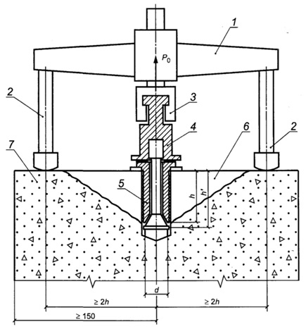
1 - device with a loading device and a force meter; 2 - support of the loading device; 3 - capture of the loading device; 4 - transitional elements, traction; 5 - anchor device; 6 - tear-out concrete (separation cone); 7 - test design
"Figure A.1 - Schematic of the shear-pull test"
A.4 The standard shearing test scheme provides for the use of three types of anchor devices (see Figure A.2). Anchor device type I is installed in the structure during concreting. Anchor devices of types II and III are installed in holes previously prepared in the structure.

1 - working rod: 2 - working rod with expanding cone; 3 - segmented corrugated cheeks; 4 - support rod; 5 - working rod with a hollow expanding cone; 6 - leveling washer
"Figure A.2 - Types of anchor devices for a standard test scheme"
A.5 Parameters of anchor devices and permissible ranges for them of measured concrete strength at standard scheme tests are listed in Table A.1. For lightweight concrete, in the standard test scheme, only anchor devices with a embedment depth of 48 mm are used.
Table A.1 - Parameters of anchor devices for a standard test scheme
|
Type of anchor device |
Embedment depth of anchor devices, mm |
Permissible range of concrete compressive strength measurements for the anchor device, MPa |
|||
|
working h |
severe | ||||
A.6 Anchor designs of types II and III should provide preliminary (before applying the load) compression of the hole walls at the working depth of embedding h and control of slippage after testing.
Annex B
(mandatory)
Standard Rib Shearing Test Arrangement
B.1 The standard scheme of testing by the rib shearing method provides for testing subject to the requirements of B.2 - B.4.
B.2 The standard test scheme is applicable in the following cases:
The maximum fraction of coarse concrete aggregate is not more than 40 mm;
Tests of heavy concrete with compressive strength from 10 to 70 MPa on crushed granite and limestone.
B.3 For testing, a device is used, consisting of a power exciter with a force measuring unit and a gripper with a bracket for local shearing of the structure rib. The test scheme is shown in Figure B.1.
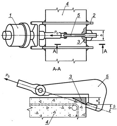
1 - device with a loading device and a force meter; 2 - support frame; 3 - chipped concrete; 4 - test design. 5 - grip with bracket
"Figure B.1 - Scheme of the rib shearing test"
B.4 In case of local shearing of the rib, the following parameters should be provided:
Depth of chipping a = (20 ± 2) mm;
Cleaving width b = (30±0.5) mm;
The angle between the direction of the load and the normal to the loaded surface of the structure β = (18±1)°.
Calibration dependence for the pull-off method with shearing in the standard test scheme
When carrying out tests by the method of separation with shearing according to the standard scheme in accordance with Appendix A, the cubic compressive strength of concrete R, MPa, can be calculated from the calibration dependence according to the formula
where m 1 - coefficient taking into account maximum size coarse filler in the pull-out zone and taken equal to 1 with a filler size of less than 50 mm;
m 2 - coefficient of proportionality for the transition from the pull-out force in kilonewtons to the strength of concrete in megapascals;
P - pull-out force of the anchor device, kN.
When testing heavy concrete with a strength of 5 MPa or more and lightweight concrete with a strength of 5 to 40 MPa, the values of the proportionality factor m 2 are taken from Table B.1.
Table B.1
|
Type of anchor device |
Range of measured concrete compressive strength, MPa |
Anchor device diameter d, mm |
Depth of embedding of the anchor device, mm |
The value of the coefficient m 2 for concrete |
|
|
severe | |||||
The coefficients m 2 when testing heavy concrete with an average strength above 70 MPa should be taken according to GOST 31914.
Calibration dependence for the rib shearing method with a standard test scheme
When performing a rib shearing test according to the standard scheme in accordance with Appendix B, the cubic compressive strength of concrete on granite and lime rubble R, MPa, can be calculated from the calibration dependence according to the formula
R=0.058m(30P+P2),
where m is a coefficient that takes into account the maximum size of coarse aggregate and is taken equal to:
1, 0 - with aggregate size less than 20 mm;
1, 05 - with aggregate size from 20 to 30 mm;
1, 1 - with aggregate size from 30 to 40 mm;
P - shearing force, kN.
Annex D
(mandatory)
Requirements for instruments for mechanical testing
Table E.1
|
Name of characteristics of devices |
Characteristics of devices for the method |
|||||
|
elastic rebound |
shock impulse |
plastic deformation |
chipping ribs |
breakaway with chipping |
||
|
Hardness of striker, striker or indenter HRCe, not less than | ||||||
|
Roughness of the contact part of the striker or indenter, µm, not more than | ||||||
|
Impactor or indenter diameter, mm, not less than | ||||||
|
Thickness of disk indenter edges, mm, not less than | ||||||
|
Conical indenter angle | ||||||
|
Indentation diameter, % of indenter diameter | ||||||
|
Perpendicularity tolerance when applying a load at a height of 100 mm, mm | ||||||
|
Impact energy, J, not less than | ||||||
|
Load increase rate, kN/s | ||||||
|
Load measurement error, %, no more | ||||||
|
* When pressing the indenter into the concrete surface. |
||||||
Method for establishing, correcting and evaluating the parameters of calibration dependencies
E.1 Calibration equation
The equation of dependence "indirect characteristic - strength" is taken as linear by the formula
E.2 Rejection of test results
After constructing the calibration dependence according to formula (E.1), it is corrected by rejecting single test results that do not satisfy the condition:
where R i n is the strength of concrete in i-th section determined by the considered calibration dependence;
S - residual standard deviation, calculated by the formula
 ,
,
here R i f, N - see the explication to the formula (E.3).
After rejection, the calibration dependence is established again according to formulas (E.1) - (E.5) according to the remaining test results. The rejection of the remaining test results is repeated, considering the fulfillment of condition (E.6) when using a new (corrected) calibration dependence.
Particular values of concrete strength must meet the requirements of 6.1.7.
E.3 Parameters of calibration dependence
For the accepted calibration dependence, determine:
Minimum and maximum value indirect characteristic H min , H max ;
Standard deviation S T . H. M of the constructed calibration dependence according to the formula (E.7);
Correlation coefficient of the calibration dependence r according to the formula
 ,
,
where the average value of concrete strength according to the calibration dependence R̅ n is calculated by the formula
here the values R i n, R i f, R̅ f, N - see the explications to formulas (E.3), (E.6).
E.4 Correction of the calibration dependence
Adjustment of the established calibration dependence, taking into account additionally obtained test results, should be carried out at least once a month.
When adjusting the calibration dependence, at least three new results obtained at the minimum, maximum and intermediate values of the indirect indicator are added to the existing test results.
As data is accumulated to build a calibration dependence, the results of previous tests, starting from the very first, are rejected so that total number results did not exceed 20. After adding new results and rejecting old ones, the minimum and maximum values of the indirect characteristic, the calibration dependence and its parameters are set again according to formulas (E.1) - (E.9).
E.5 Conditions for applying the calibration dependence
The use of a calibration dependence to determine the strength of concrete according to this standard is allowed only for values of an indirect characteristic falling in the range from H min to H max.
If the correlation coefficient r< 0, 7 или значение S T . H . M / R̅ ф >0, 15, then control and strength assessment based on the obtained dependence are not allowed.
Annex G
(mandatory)
The method of binding the calibration dependence
G.1 The value of the strength of concrete, determined using the calibration dependence established for concrete that differs from the test, is multiplied by the coefficient of coincidence K c. The value of K with is calculated by the formula
![]() ,
,
where R os i is the strength of concrete in the i-th section, determined by the method of separation with chipping or testing of cores according to GOST 28570;
R cos i - strength of concrete in the i-th section, determined by any indirect method according to the calibration dependence used;
n is the number of test sites.
G.2 When calculating the coefficient of coincidence, the following conditions must be met:
The number of test sites taken into account when calculating the coefficient of coincidence, n ≥ 3;
Each private value R os i /R cos i must be at least 0.7 and not more than 1.3:
![]() ;
;
Each private value R os i /R cos i must differ from the average value by no more than 15%:
![]() .
.
Values R os i /R cos i that do not satisfy the conditions (G.2), (G.3) should not be taken into account when calculating the coefficient of coincidence K with.
Assignment of the number of test sites for prefabricated and monolithic structures
I.1 In accordance with GOST 18105, when testing the strength of concrete of prefabricated structures (tempering or transfer), the number of controlled structures of each type is taken at least 10% and at least 12 structures from the batch. If the batch consists of 12 structures or less, complete control is carried out. In this case, the number of sections must be at least:
1 per 4 m length of linear structures;
1 by 4 m 2 area of flat structures.
I.2 In accordance with GOST 18105, when testing the strength of concrete of monolithic structures at an intermediate age, at least one structure of each type (column, wall, ceiling, crossbar, etc.) from the controlled batch is controlled by non-destructive methods.
I.3 In accordance with GOST 18105, when checking the strength of concrete of monolithic structures at the design age, continuous non-destructive testing of the strength of concrete of all structures of the controlled batch is carried out. In this case, the number of test sites must be at least:
3 for each grip for flat structures (wall, floor, foundation slab);
1 per 4 m length (or 3 per grip) for each line horizontal design(beam, crossbars);
6 per design - for linear vertical structures(column, pylon).
The total number of measurement sites for calculating the characteristics of the uniformity of the strength of concrete of a batch of structures should be at least 20.
I.4 The number of single measurements of the strength of concrete by mechanical methods of non-destructive testing in each section (the number of measurements in the section) is taken according to table 2.
Test result presentation table form
|
Name of structures (batch of structures), design class of concrete strength, date of concreting or age of concrete of tested structures |
Designation(1) |
N plot according to the scheme or location in the axes (2) |
Strength of concrete, MPa |
Concrete strength class(5) |
|
|
plot(3) |
medium(4) |
||||
|
(1) brand, symbol and (or) the location of the structure in the axes, the zone of the structure, or part of the monolithic and precast-monolithic structure (grip), for which the concrete strength class is determined. (2) Total number and location of sites in accordance with 7.1.1. (3) Strength of site concrete in accordance with 7.1.5. (4) The average strength of the concrete of a structure, a zone of a structure, or a part of a monolithic and cast-in-place structure for the number of sections that meet the requirements of 7.1.1. (5) The actual strength class of concrete of a structure or part of a monolithic and precast-monolithic structure in accordance with paragraphs 7.3 - 7.5 of GOST 18105, depending on the selected control scheme. Note - The presentation in the column "Concrete strength class" of the estimated values of the class or values \u200b\u200bof the required concrete strength for each section separately (estimation of the strength class for one section) is not allowed. |
|||||
V.A. Klevtsov, Dr. tech.. sciences (topic leader); M.G. Korevitskaya, Ph.D. tech. sciences; Yu.K.Matveev; V.N. Artamonova; N.S. Vostrova; A.A. Grebenik; G.V. Sizov, Ph.D. tech. sciences; D.A. Korshunov, Ph.D. tech. sciences; M.V. Sidorenko, Ph.D. tech. sciences; Yu.I.Kurash, Ph.D. tech. sciences; A.M. Leshchinsky, Ph.D. tech. sciences; V.R. Abramovsky; V.A.Dorf, Ph.D. tech. sciences; E.G. Sorkin, Ph.D. tech. sciences; V.L. Chernyakhovsky, Ph.D. tech. sciences; I.O. Krol, Ph.D. tech. sciences; S.Ya.Khomutchenko; Ya.E. Ganin; O.Yu.Sammal, Ph.D. tech. sciences; A.A. Rulkov, Ph.D. tech. sciences; P.L. Talberg; A.I.Markov, Ph.D. tech. sciences; R.O. Krasnovsky, Ph.D. tech. sciences; L.S. Pavlov, Ph.D. tech. sciences; M.Yu. Leshchinsky, Ph.D. tech. sciences; G.A. Tselykovsky; I.E. Shkolnik, Ph.D. tech. sciences; T.Yu.Lapenis, G.I. Weingarten, Ph.D. tech. sciences; N.B. Zhukovskaya; S.P. Abramova; I.N. Nagornyak
This International Standard applies to heavy and lightweight concrete and specifies methods for determining the compressive strength of structures in terms of rebound, impact impulse, plastic deformation, peeling, rib shearing, and shearing shear.
Dimensions of the imprint on concrete (diameter, depth, etc.) or the ratio of the diameters of imprints on concrete and a standard sample when the indenter is struck or the indenter is pressed into the concrete surface;
The value of the stress required for local destruction of concrete when a metal disk glued to it is torn off, equal to the tear force divided by the projection area of the concrete torn-off surface onto the disk plane;
1.3. Mechanical methods of non-destructive testing are used to determine the strength of concrete of all types of normalized strength, controlled in accordance with GOST 18105, as well as to determine the strength of concrete during examination and rejection of structures.
1.4. Tests are carried out at a positive temperature of concrete. When examining structures, it is allowed to determine the strength at a negative temperature, but not lower than minus 10 ° C, provided that by the time of freezing, the structure has been at a positive temperature for at least one week and relative humidity air no more than 75%.
1.5. The assessment of the conformity of the values of the actual strength of concrete, obtained using the methods given in this standard to the established requirements, is carried out in accordance with GOST 18105.
2.1. The strength of concrete is determined using instruments designed to determine indirect characteristics that have passed metrological certification in accordance with GOST 8.326* and meet the requirements given in Table 2.
| Name of characteristics of devices | Characteristics of devices for the method | |||||
| elastic rebound | shock impulse | plastic deformation | separation | chipping ribs | breakaway with chipping | |
| Hardness of striker, striker or indenter HRCe, not less than | ||||||
| Roughness of the contact part of the striker or indenter, µm, not more than | ||||||
| Impactor or indenter diameter, mm, not less than | ||||||
| Thickness of disk indenter edges, mm, not less than | 10 | |||||
| Conical indenter angle | 30-60° | |||||
| Indentation diameter, % of indenter diameter | 20-70 | |||||
| Perpendicularity tolerance when applying a load at a height of 100 mm, mm |
||||||
| Impact energy, J, not less than | 0,02 | |||||
| Load increase rate, kN/s | 1,5* | 0,5-1,5 | 0,5-1,5 | 1,5-3,0 | ||
| Load measurement error from the measured load, %, no more | 5* | |||||
2.2. A tool for measuring the diameter or depth of indentations (angular scale according to GOST 427, caliper according to GOST 166, etc.) used for the plastic deformation method must provide measurements with an error of no more than ±0.1 mm, and a tool for measuring the depth of an indentation (indicator clock type according to GOST 577, etc.) - with an error of not more than ± 0.01 mm.
It is also allowed to use other anchor devices, the insertion depth of which should not be less than the maximum size of the coarse concrete aggregate of the structure being tested.
2.5. For the tear-off method, steel discs with a diameter of at least 40 mm, a thickness of at least 6 mm and at least 0.1 diameter, with a roughness parameter of the glued surface of at least 20 microns in accordance with GOST 2789, should be used. The adhesive for gluing the disc must provide strength at which
3.1. To determine the strength of concrete in structures, a calibration relationship is first established between the strength of concrete and an indirect characteristic of strength (in the form of a graph, table or formula).
For the tear-off method with shearing, in the case of using anchor devices in accordance with Appendix 2, and for the shearing method of the rib, in the case of using devices in accordance with Appendix 3, it is allowed to use the calibration dependences given in Appendixes 5 and 6, respectively.
The method of detachment with shearing occupies a special place among the methods for determining the strength of concrete. Considered a non-destructive method, the shearing method is inherently a destructive concrete testing method, as the strength of concrete is estimated by the force required to break a small volume of concrete, which allows the most accurate assessment of its actual strength. Therefore, this method is used not only to determine the strength of concrete of unknown composition, but can also be used to build calibration dependencies for other non-destructive testing methods. This method is applied to heavy concrete and structural concrete on light aggregates in monolithic and prefabricated concrete and reinforced concrete products, structures and structures and establishes a method for testing concrete and determining its compressive strength by local destruction of concrete when a special anchor device is pulled out of it. This method of testing concrete with shearing makes it possible to determine the compressive strength for concrete in the strength range from 5.0 to 100.0 MPa. When developing the standard, materials GOST 22690-88 were used.
One of the most common and effective ways a quick measurement of the compressive strength of concrete or its grade is a measurement with a sclerometer, or as it is also called, a Schmidt hammer.
Conformity of the Grade and Class of concrete to the readings of the scale of the sclerometer (Schmidt hammer) in the direction of impact in accordance with the chart of the calibration curve
Concrete brand, M Concrete class,
B Vertical top, u Horizontal, u Vertically from below, units
M100 7.5 10 13 20
- 10 12 18 23
M150 12.5 20 24 28
M200 15 24 28 32
М250 20 30 34 38
M300 22.5 34 37 41
M350 27.5 38 41 45
М400 30 41 43 47
М450 35 44 47 50
М500 40 47 49 52
M600 45 49 52 55
GOST 10180-90 Concrete. Methods for determining the strength of control samples
GOST 18105-86 Concrete. Strength control rules
GOST 22690-88 Concrete. Determination of strength by mechanical methods of non-destructive testing
Another method for testing concrete is shearing. This method consists in determining the degree of force that is necessary to chip off a section of concrete on the edge of the structure. Sometimes this method consists in the local destruction of concrete: within the framework of this method, the anchor device breaks out. The chipping method is the most accurate, but also the most time-consuming method of control, since the preparation of special holes is required for the installation of the anchor. Moreover, this method is not universal enough: it is not applicable in series of structures.
"Prometheus" recommends a method for determining the strength of concrete by separation with shearing in field surveys. Such methods of testing concrete by detachment are also ideal for surveying at the stages of construction, acceptance, operation and reconstruction of building objects, as well as for the manufacture of prefabricated products at enterprises producing reinforced concrete products.
Testing the mechanical properties of concrete in the laboratory
For materials such as concrete, the determination of strength by mechanical methods of non-destructive testing is desirable to control the reliability of the results by comparing data obtained directly and indirectly. This kind of research is carried out by the mechanical testing laboratory at Prometey LLC.
Under laboratory conditions, physical and mechanical tests of concrete samples are carried out using all known approaches, including the basic destructive method of concrete control, shock impulse and elastic rebound methods. It is important that the measurements are carried out by a qualified mechanical test technician - the influence of the human factor should be minimized.
As shown by mechanical testing of materials, indirect methods of mechanical testing overestimate the strength characteristics of carbonized concrete by 40–60%, and the method of separation with chipping is recognized as the most reliable.
Sheared pull-off method: advantages and limitations
All modern standards include in the program of full-scale inspections of reinforced concrete structures mechanical tests of concrete with shearing.
In practice, shear-off provides a number of advantages:
- the ability to install devices on flat areas without a rib;
- independence from power supply;
- tolerance for low temperatures;
- control of the strength of concrete class B50 and above;
- fast and convenient mounting of equipment.
If the curvature of the block does not prevent the connection of the device to the anchor, the determination of the strength of concrete by detachment with shearing can also be carried out on uneven concrete surfaces(from 5 mm). The dense reinforcement of concrete makes it difficult to test for mechanical strength using this method; at the same time, the thickness of the concrete in the measurement area should not be less than twice the length of the anchor.
Used equipment
POS-50MG4 "Skol" is designed for non-destructive testing of concrete strength by methods of rib chipping, tearing with chipping and tearing of steel disks according to GOST 22690-88.
INTERSTATE COUNCIL FOR STANDARDIZATION, METROLOGY AND CERTIFICATION
INTERSTATE COUNCIL FOR STANDARDIZATION, METROLOGY AND CERTIFICATION
INTERSTATE
STANDARD
CONCRETE
Determination of strength by mechanical methods of non-destructive testing
(EN 12504-2:2001, NEQ)
(EN 12504-3:2005, NEQ)
Official edition
Stand rtinform 2016
Foreword
The goals, basic principles and basic procedure for carrying out work on the interstate camp, darting are established by GOST 1.0-92 “Interstate standardization system. Basic Provisions” and GOST 1.2-2009 “Interstate Standardization System. Interstate standards. rules and recommendations for interstate standardization. Rules for the development, adoption, application, updating and cancellation "
About the standard
1 DEVELOPED by the Structural Subdivision of JSC "NIC "Construction" Research. Design and Technological Institute of Concrete and Reinforced Concrete. A.A. Gvozdev (NIIZhB)
2 INTRODUCED by the Technical Committee for Standardization TC 465 "Construction"
3 ADOPTED by the Interstate Council for Standardization, Metrology and Certification (Minutes of June 18, 2015 No. 47)
4 By order of the Federal Agency for Technical Regulation and Metrology dated September 25, 2015 No. 1378-st, the interstate standard GOST 22690-2015 was put into effect as the national standard of the Russian Federation from April 1, 2016.
5 8 this standard takes into account the main regulatory provisions regarding the requirements for mechanical methods of non-destructive testing of the strength of concrete of the following European regional standards:
EN 12504-2:2001 Testing concrete in structures - Part 2: Non-destructive testing - Determination of rebound number
EN 12504-3:2005 Testing concrete in structures - Determination of pull-out force.
Degree of conformity - non-equivalent (NEQ)
6 83AMEN GOST 22690-88
Information about changes to this standard is published in the annual information index "National Standards", and the text of changes and amendments - in the monthly information index "National Standards". In case of revision (replacement) or cancellation of this standard, a corresponding notice will be published in the monthly information index *National Standards. Relevant information, notification and texts are also posted in the public information system - on the official website of the Federal Agency for Technical Regulation and Metrology on the Internet
© Standartinform. 2016
In the Russian Federation, this standard may not be fully or partially reproduced. replicated and distributed as an official publication without the permission of the Federal Agency for Technical Regulation and Metrology
Annex A (normative) Standard scheme for the pull-and-shear test. . . ten

INTERSTATE STANDARD
Determination of strength by mechanical methods of non-destructive testing
Determination of strength by mechanical methods of nondestructive testing
Introduction date - 2016-04-01
1 area of use
This standard applies to structural heavy, fine-grained, light and tension concrete of monolithic, precast and precast-monolithic concrete and reinforced concrete products. structures and structures (hereinafter referred to as structures) and establishes mechanical methods for determining the compressive strength of concrete in structures by elastic rebound, shock impulse, plastic deformation, separation, chipping of the rib and tearing with chipping.
8 of this standard, normative references to the following interstate standards are used:
GOST 166-89 (ISO 3599-76) Calipers. Specifications
GOST 577-68 Clock-type indicators with a division stage of 0.01 mm. Specifications
GOST 2789-73 Surface roughness. Parameters and characteristics
GOST 10180-2012 Concrete. Methods for determining the strength of control samples
GOST 18105-2010 Concrete. Strength control and assessment rules
GOST 28243-96 Pyrometers. General technical requirements
GOST 28570-90 Concrete. Methods for determining strength from samples taken from structures
GOST 31914-2012 High-strength heavy and fine-grained concretes for monolithic structures. Rules for quality control and assessment
Note - When using this standard, it is advisable to check the validity of reference standards in the public information system - not the official website of the Federal Agency for Technical Regulation and Metrology on the Internet or according to the annual information index "National Standards", which was published as of January 1 of the current year, and on issues of the monthly information index "National Standards" for the current year. If the reference standard is replaced (modified), then when using this standard, you should be guided by the replacing (modified) standard. If the referenced standard is canceled without replacement, the provision in which the reference to it is given applies to the extent that this reference is not affected.
3 Terms and definitions
8 of this standard, the terms are used in accordance with GOST 18105. as well as the following terms with the corresponding definitions:
Official edition
destructive methods for determining the strength of concrete: Determination of the strength of concrete according to control samples made from a concrete mix according to GOST 10180 or selected from structures according to GOST 28570.
[GOST 18105-2010. article 3.1.18]
3.2 non-destructive mechanical methods for determining the strength of concrete: Determination of the strength of concrete directly in the structure under local mechanical action on concrete (impact, separation, chipping, indentation, separation with chipping, elastic rebound).
3.3 indirect non-erosion methods for determining the strength of concrete: Determination of the strength of concrete according to pre-established calibration dependencies.
3.4 direct (standard) non-destructive methods for determining the strength of concrete: Methods that provide standard test schemes (tearing off with shearing and shearing of the rib) and allowing the use of known calibration dependencies without reference and adjustment
3.5 calibration dependence: Graphical or analytical dependence between the indirect strength characteristic and the compressive strength of concrete, determined by one of the destructive or direct non-destructive methods.
3.6 indirect strength characteristics (indirect indicator): The magnitude of the applied force during local destruction of concrete, the magnitude of the rebound, the impact energy, the size of the imprint or other indication of the device when measuring the strength of concrete by non-destructive mechanical methods.
4 General provisions
4.1 Non-destructive mechanical methods are used to determine the compressive strength of concrete at the intermediate and design age established by the design documentation and at an age exceeding the design age when examining structures.
4.2 Non-destructive mechanical methods for determining the strength of concrete, established by this standard, are divided according to the type of mechanical action or indirect characteristic determined by the method:
Elastic rebound;
plastic deformation;
> shock impulse:
Breakaway with chipping:
Rib chipping.
4.3 Non-erosion mechanical methods for determining the strength of concrete are based on the relationship between the strength of concrete and indirect strength characteristics:
The method of elastic rebound on the relationship between the strength of concrete and the value of the rebound of the striker from the surface of the concrete (or the striker pressed against it);
The method of plastic deformation in relation to the strength of concrete with the dimensions of the imprint on the concrete of the structure (diameter, depth, etc.) or the ratio of the diameter of the imprint on concrete and a standard metal sample when the indenter is struck or the indenter is pressed into the concrete surface;
Impact impulse method on the relationship between the strength of concrete and the energy of impact and its changes at the moment of impact of the striker with the concrete surface;
The method of tearing off the tension bond required for local destruction of concrete when a metal disk glued to it is torn off, equal to the tearing force divided by the projection area of the concrete tearing surface onto the plane of the disk;
Method of detachment with shearing on the connection of the strength of concrete with the value of the force of local destruction of concrete when the anchor device is excavated from it;
Rib shearing method on the relationship of concrete strength with the value of the force required to shear a section of concrete on a structure edge.
4.4 In general, non-destructive mechanical methods for determining the strength of concrete are indirect non-destructive methods for determining strength. The strength of concrete in structures is determined by experimentally established calibration dependencies.
4.5 The tear-off method with shearing during testing in accordance with the standard scheme in Appendix A and the method of shearing off the rib during testing in accordance with the standard scheme in Appendix B are direct non-destructive methods for determining the strength of concrete. For direct non-destructive methods, it is allowed to use the calibration dependences established in Appendixes b and D.
Note - Standard test schemes are applicable for a limited range of concrete strength (see Annexes A and B). For cases not related to standard test schemes, calibration dependencies should be established according to general rules.
4.6 The test method should be selected taking into account the data given in Table 1. and additional restrictions established by manufacturers of specific measuring instruments. The use of methods outside the concrete strength ranges recommended in Table 1 is allowed with scientific and technical justification based on the results of studies using measuring instruments that have passed metrological certification for an extended concrete strength range.
Table 1
4.7 Determination of the strength of heavy concrete of design classes B60 and above or with an average compressive strength of concrete R m i 70 MPa in monolithic structures must be carried out taking into account the provisions of GOST 31914.
4.8 The strength of concrete is determined in sections of structures that do not have visible damage (peeling of the protective layer, cracks, cavities, etc.).
4.9 The age of concrete of controlled structures and its sections should not differ from the age of concrete of structures (sections, samples) tested to establish a calibration dependence by more than 25%. The exceptions are the control of strength and the construction of a calibration dependence for concrete whose age exceeds two months. In this case, the difference in the age of individual structures (sections, samples) is not regulated.
4.10 Tests are carried out at a positive temperature of concrete. It is allowed to conduct tests at a negative temperature of concrete, but not lower than minus 10 "C, when establishing or linking a calibration dependence taking into account the requirements of 6.2.4. The temperature of the concrete during testing must correspond to the temperature provided for by the operating conditions of the devices.
Calibration dependencies established at a concrete temperature below 0 * C are not allowed to be used at positive temperatures.
4.11 If it is necessary to test concrete structures after heat treatment at a surface temperature of T to 40 * C (to control the tempering, transfer and stripping strength of concrete), the calibration dependence is established after determining the strength of concrete in the structure by an indirect non-destructive method at a temperature (t (T ± 10) *C, and testing of concrete by a direct non-destructive method or testing of samples - after cooling at normal temperature.
5 Measuring instruments, equipment and tools
5.1 Measuring instruments and devices for mechanical testing, designed to determine the strength of concrete, must be certified and verified in the prescribed manner and must comply with the requirements of Appendix D.
5.2 Readings of instruments calibrated in units of concrete strength should be considered as an indirect indicator of concrete strength. These devices should only be used after
establishing a calibration dependence "instrument reading - concrete strength" or linking the dependence established in the device in accordance with 6.1.9.
5.3 A tool for measuring the diameter of indentations (caliper according to GOST 166) used for the plastic deformation method should provide measurement with an error of no more than 0.1 mm. a tool for measuring the depth of an imprint (a dial indicator according to GOST 577, etc.) - with an error of no more than 0.01 mm.
5.4 Standard schemes for testing the method of separation with shearing and spalling of the rib provide for the use of anchor devices and grips in accordance with Annexes A and B.
5.5 For the chipping method, anchor devices should be used. the embedment depth of which shall not be less than the maximum size of the coarse concrete aggregate of the structure being tested.
5.6 For the pull-off method, steel discs with a diameter of at least 40 mm should be used. not less than 6 mm thick and not less than 0.1 diameter, with the roughness parameters of the bonded surface not less than Ra = 20 µm according to GOST 2789. The adhesive for gluing the disc must provide adhesion to concrete, at which destruction occurs along concrete.
6 Test preparation
6.1 Procedure for preparing for testing
6.1.1 Preparation for testing includes checking the instruments used in accordance with the instructions for their operation and establishing calibration dependencies between the concrete strength and the indirect strength characteristic.
6.1.2 The calibration dependence is established on the basis of the following data:
The results of parallel tests of the same sections of structures by one of the indirect methods and the direct non-destructive method for determining the strength of concrete;
The results of testing sections of structures by one of the indirect non-destructive methods for determining the strength of concrete and testing core samples taken from the same sections of the structure and tested in accordance with GOST 28570:
The results of testing standard concrete samples by one of the indirect non-destructive methods for determining the strength of concrete and mechanical tests in accordance with GOST 10180.
6.1.3 For indirect non-destructive methods for determining the strength of concrete, the calibration dependence is established for each type of normalized strength specified in 4.1 for concretes of the same nominal composition.
It is allowed to build one calibration dependence for concrete of the same type with one type of coarse aggregate, with a single production technology, differing in nominal composition and normalized strength value, subject to the requirements of 6.1.7
6.1.4 The permissible difference in the age of concrete of individual structures (sections, samples) when establishing a calibration dependence on the age of concrete of a controlled structure is taken according to 4.9.
6.1.5 For direct non-destructive methods according to 4.5, it is allowed to use the dependencies given in Appendices C and D for all types of normalized concrete strength.
6.1.6 The calibration dependence must have a standard (residual) deviation S T n m not exceeding 15% of the average concrete strength of the sections or samples used in the construction of the dependence, and the correlation coefficient (index) of at least 0.7.
It is recommended to use a linear relationship of the form R * a * bK (where R is the strength of concrete. K is an indirect indicator). The methodology for establishing, estimating parameters and determining the conditions for applying a linear calibration dependence is given in Appendix E.
6.1.7 When constructing the calibration dependence of the deviation of individual values of concrete strength R^ from the average value of the concrete strength of sections or samples R f. used to build the calibration dependence should be within:
> from 0.5 to 1.5 average concrete strength Rf at Rf £20 MPa;
From 0.6 to 1.4 average concrete strength R, f at 20 MPa< Я ф £50 МПа;
From 0.7 to 1.3 average concrete strength R f at 50 MPa<Я Ф £80 МПа;
From 0.8 to 1.2 the average value of concrete strength R f at R f > 80 MPa.
6.1.8 Correction of the established dependence for concretes of intermediate and design age should be carried out at least once a month, taking into account additionally obtained test results. The number of samples or areas of additional tests during the adjustment should be at least three. The correction method is given in Appendix E.
6.1.9 It is allowed to use indirect non-destructive methods for determining the strength of concrete, using calibration dependencies established for concrete that differs from the tested one in composition, age, hardening conditions, humidity, with reference in accordance with the method according to the principle of Zh.
6.1.10 Without reference to specific conditions according to Appendix G, the calibration dependences established for concrete that differs from the tested one can only be used to obtain approximate strength values. It is not allowed to use approximate strength values without reference to specific conditions to assess the strength class of concrete.
6.2 Construction of a calibration dependence based on the results of concrete strength tests
in designs
6.2.1 When constructing a calibration dependence based on the results of testing the strength of concrete in structures, the dependence is established by single values of the indirect indicator and concrete strength of the same sections of structures.
For a single value of the indirect indicator, the average value of the indirect indicator in the area is taken. For a single value of the strength of concrete, the strength of the concrete of the site, determined by a direct non-destructive method or testing of selected samples, is taken.
6.2.2 The minimum number of single values for constructing a calibration dependence based on the results of testing the strength of concrete in structures is 12.
6.2.3 When constructing a calibration dependence based on the results of testing the strength of concrete in structures not subject to testing, structures or their zones, preliminary measurements are carried out by an indirect non-destructive method in accordance with the requirements of Section 7.
Then, sections are selected in the number provided for in 6.2.2, on which the maximum is obtained. minimum and intermediate values of the indirect indicator.
After testing by an indirect non-destructive method, the sections are tested by a direct non-destructive method or samples are taken for testing in accordance with GOST 26570.
6.2.4 To determine the strength at a negative temperature of concrete, the sections selected for constructing or linking the calibration dependence are first tested by an indirect non-erosion method, and then samples are taken for subsequent testing at a positive temperature or heated by external heat sources (infrared emitters, heat guns and etc.) to a depth of 50 mm to a temperature not lower than 0 * C and tested by a direct non-destructive method. The temperature control of the heated concrete is carried out at the depth of installation of the anchor device in the prepared hole or along the surface of the chip in a non-contact way using a pyrometer according to GOST 28243.
Rejection of the test results used to build the calibration dependence at a negative temperature is allowed only if the deviations are associated with a violation of the test procedure. In this case, the rejected result should be replaced by the results of a repeated test in the same area of the structure.
6.3 Construction of a calibration dependence on control samples
6.3.1 When constructing a calibration dependence on control samples, the dependence is established by single values of the indirect indicator and concrete strength of standard cube samples.
For a single value of the indirect indicator, the average value of the indirect indicators for a series of samples or for one sample (if the calibration dependence is established for individual samples) is taken. For a single value of the strength of concrete, the strength of concrete in a series according to GOST 10180 or one sample (calibration dependence for individual samples) is taken. Mechanical testing of samples according to GOST 10180 is carried out immediately after testing by an indirect non-destructive method.
6.3.2 When constructing a calibration dependence based on the results of testing sample cubes, at least 15 series of sample cubes according to GOST 10180 or at least 30 individual sample cubes are used. Samples are made in accordance with the requirements of GOST 10180 in different shifts, for at least 3 days from concrete of the same nominal composition, according to the same technology, with the same hardening mode as the structure to be controlled.
The unit values of the concrete strength of the sample cubes used to build the calibration dependence must correspond to the deviations expected in production, while being within the ranges established in 6.1.7.
6.3.3 The calibration dependence for the methods of elastic rebound, shock impulse, plastic deformation, separation and chipping of the rib is established on the basis of the results of testing the manufactured sample cubes, first by the non-destructive method, and then by the destructive method in accordance with GOST 10180.
When establishing a calibration dependence for the tear-off method with shearing, the main and control samples are made according to 6.3.4. An indirect characteristic is determined on the main samples. control samples are tested in accordance with GOST 10180. The main and control samples must be made from the same concrete and harden under the same conditions.
6.3.4 The dimensions of the samples should be selected in accordance with the largest aggregate size in the concrete mixture in accordance with GOST 10180. but not less than:
100* 100* 100 mm for rebound, shock impulse, plastic deformation methods. as well as for the method of separation with chipping (control samples);
200*200*200mm for design rib chipping method:
300*300*300mm. but with a rib size of at least six anchor device installation depths for the pull-off method with shearing (basic samples).
6.3.5 To determine the indirect strength characteristics, tests are carried out in accordance with the requirements of Section 7 on the side (in the direction of concreting) faces of the sample cubes.
The total number of measurements on each sample for the method of elastic rebound, shock impulse, plastic deformation upon impact must be at least the established number of tests in the area according to Table 2. and the distance between the impact points must be at least 30 mm (15 mm for the shock impulse method). For the indentation plastic deformation method, the number of tests on each face must be at least two, and the distance between the test points must be at least two indent diameters.
When establishing a calibration dependence for the rib shearing method, one test is carried out on each side rib.
When establishing the calibration dependence for the method of separation with shearing, one test is carried out on each side face of the main sample.
6.3.6 When tested by the method of elastic rebound, shock impulse, plastic deformation upon impact, the specimens shall be clamped in the press with a force of not less than (30 ± 5) kN and not more than 10% of the expected value of the breaking load.
6.3.7 The specimens tested by the pull-off method are mounted on the press as follows. so that the surfaces on which the pull-out was carried out do not adjoin to the base plates of the press. The test results according to GOST 10180 are increased by 5%.
7 Testing
7.1 General requirements
7.1.1 The number and location of controlled sections in structures must comply with the requirements of GOST 18105 and be indicated in the design documentation for structures or be set taking into account:
Control tasks (determining the actual class of concrete, stripping or tempering strength, identifying areas of reduced strength, etc.);
Type of construction (columns, beams, slabs, etc.);
Placement of grips and pouring order:
Structural reinforcement.
The rules for assigning the number of test sites for monolithic and prefabricated structures in the control of concrete strength are given in Appendix I. When determining the strength of concrete of the examined structures, the number and location of the sections should be taken according to the survey program.
7.1.2 Tests are carried out on a construction site with an area of 100 to 900 cm2.
7.1.3 The total number of measurements in each area, the distance between the measurement points in the area and from the edge of the structure, the thickness of the structures in the measurement area should not be less than the values given in Table 2, depending on the test method.
Table 2 - Requirements for test sites
|
Method name |
Total number of measurements per plot |
Minimum distance between measurement points on the site, mm |
Minimum distance from the edge of the structure to the measurement point, mm |
Minimum construction thickness, mm |
|
Elastic Bounce | ||||
|
shock impulse | ||||
|
Plastic deformation | ||||
|
Rib digging | ||||
|
2 disc diameters | ||||
|
Detachment with chipping at the working depth of the anchor L: * 40mm< 40мм |
7.1.4 The deviation of individual measurement results in each section from the arithmetic mean of the measurement results for this section should not exceed 10%. The results of measurements that do not meet the specified condition are not taken into account when calculating the arithmetic mean of the indirect indicator for this area. The total number of measurements in each section when calculating the arithmetic mean must comply with the requirements of Table 2.
7.1.5 The strength of concrete in the controlled section of the structure is determined by the average value of the indirect indicator according to the calibration dependence established in accordance with the requirements of Section 6. provided that the calculated value of the indirect indicator is within the established (or tied) dependence (between the smallest and largest values strength).
7.1.6 The surface roughness of the structure concrete section when tested by the methods of rebound, impact impulse, plastic deformation should correspond to the surface roughness of the structure sections (or cubes) tested when establishing the calibration dependence. In necessary cases, it is allowed to clean the surfaces of the structure.
When using the indentation plastic deformation method, if the zero reading is taken after the application of the initial load, there are no requirements for the roughness of the concrete surface of the structure.
7.2 Rebound method
7.2.1 Tests are carried out in the following sequence:
The position of the device when testing the structure relative to the horizontal is recommended to be taken the same. as well as when establishing the calibration dependence. In a different position of the device, it is necessary to make a correction for the indicators in accordance with the instruction manual for the device:
7.3 Plastic deformation method
7.3.1 Tests are carried out in the following sequence:
The device is positioned so that the force is applied perpendicular to the surface under test in accordance with the instructions for use of the device;
When using a spherical indemtor to facilitate measurements of the diameters of prints, the test can be carried out through sheets of carbon paper and white paper (in this case, tests to establish the calibration dependence should be carried out using the same paper);
Fix the values of the indirect characteristic in accordance with the instruction manual for the device;
Calculate the average value of the indirect characteristic on the construction site.
7.4 Shock pulse method
7.4.1 Tests are carried out in the following sequence:
The device is placed like this. so that the force is applied perpendicular to the surface under test * in accordance with the instructions for use of the device:
The position of the device when testing the structure relative to the horizontal is recommended to be taken the same as when testing when establishing the calibration dependence. In a different position of the device, it is necessary to make a correction for the readings in accordance with the instruction manual for the device;
The value of the indirect characteristic is fixed in accordance with the instruction manual for the device;
Calculate the average value of the indirect characteristic on the construction site.
7.5 Pull-off method
7.5.1 When testing by the pull-off method, the sections should be located in the zone of the lowest stresses caused by the operational load or the compression force of the prestressed reinforcement.
7.5.2 The test is carried out in the following sequence:
At the place where the disk is glued, a surface layer of concrete with a depth of 0.5-1 mm is removed and the surface is cleaned of dust;
The disk is glued to the concrete by pressing the disk and removing excess adhesive outside the disk;
The ribs are connected to the disk;
The load is smoothly increased with a speed of (1 ± 0.3) kN / s;
Record the reading of the force meter of the device;
Measure the projection area of the separation surface on the plane of the disk with an error of iO.Scm 2 ;
The value of the conditional stress in the concrete at separation is determined as the slope of the maximum separation force to the area of the projection of the separation surface.
7.5.3 The test results are not taken into account if the reinforcement was exposed during the detachment of concrete or the projection area of the detachment surface was less than 80% of the disk area.
7.6 Pull-off method with shear
7.6.1 When testing by the pull-off method with shearing, the sections should be located in the zone of the lowest stresses caused by the operational load or the compression force of the prestressed reinforcement.
7.6.2 Tests are carried out in the following sequence:
If the anchor device was not installed before concreting, then a hole is made in the concrete, the size of which is chosen in accordance with the device operating instructions, depending on the type of anchor device;
An anchor device is fixed in the hole to the depth provided for in the instruction manual for the device, depending on the type of anchor device;
The device is connected with a sunker device;
The load is increased at a rate of 1.5-3.0 kN / s:
The reading of the force meter of the P 0 device and the amount of slippage of the anchor LP (the difference between the actual depth of the pull-out and the depth of the anchor device) are recorded with an accuracy of not less than 0.1 mm.
7.6.3 The measured value of the pull-out force P 4 is multiplied by the correction factor y. determined by the formula
where L is the working depth of the anchor device, mm;
DP - anchor slippage, mm.
7.6.4 If the largest and smallest dimensions of the torn out part of the concrete from the anchor device to the boundaries of destruction along the surface of the structure differ by more than two times, and also if the depth of the torn out differs from the depth of the anchor device by more than 5% (DL > 0.05ft, y > 1.1), then the test results can only be taken into account for an approximate assessment of the strength of concrete.
Note - Approximate values of the strength of concrete are not allowed to be used to assess the class of concrete in terms of strength and build calibration dependencies.
7.6.5 The test results are not taken into account if the pull-out depth differs from the anchoring device embedment depth by more than 10% (dL > 0.1 A) or the reinforcement was exposed at a distance from the anchor device less than its embedment depth.
7.7 Rib chipping method
7.7.1 When testing by the rib shearing method, there should be no cracks, concrete rims, sags or shells with a height (depth) of more than 5 mm in the test area. The sections should be located in the zone of the least stresses caused by the operational load or the compression force of the prestressed reinforcement.
7.7.2 The test is carried out in the following sequence:
The device is fastened to the structure. apply a load at a speed of no more than (1 ± 0.3) kN/s;
Record the reading of the instrument's force meter;
Measure the actual depth of chipping;
Determine the average value of the chipping force.
7.7.3 The test results are not taken into account if the reinforcement was exposed when concrete was chipped or the actual chipping depth differed from the specified one by more than 2 mm.
8 Processing and presentation of results
8.1 The test results are presented in a table indicating:
Type of construction;
Design class of concrete;
Age of concrete;
The strength of the concrete of each controlled area according to 7.1.5;
The average strength of the concrete structure;
Zones of the structure or its parts subject to the requirements of 7.1.1.
The form of the test results presentation table is given in Annex K.
8.2 The processing and assessment of compliance with the established requirements of the actual strength of concrete obtained using the methods given in this standard is carried out according to GOST 18105.
Note in h in n and in - Statistical assessment of the concrete class according to the test results is carried out in accordance with GOST 18105 (schemes "A", "B" or "C") in cases where the strength of concrete is determined by the calibration dependence built in in accordance with section 6. When using previously established dependencies by linking them (according to Appendix G), statistical control is not allowed, and the assessment of the concrete class is carried out only according to the “G” scheme of GOST 18105.
8.3 The results of determining the strength of concrete by mechanical methods of non-destructive testing are drawn up in a conclusion (protocol), in which the following data are given:
About the tested structures indicating the design class, the date of concreting and testing, or the age of concrete at the time of testing;
On the methods used to control the strength of concrete;
About the types of devices with serial numbers, information about the verification of devices;
On the accepted calibration dependences (dependence equation, dependence parameters, compliance with the conditions for applying the calibration dependence);
Used to build a calibration dependence or its binding (date and results of tests by non-destructive indirect and direct or destructive methods, correction factors);
On the number of sites for determining the strength of concrete in structures, indicating their location;
Test results;
Methodology, results of processing and evaluation of the obtained data.
Standard Shear-Pull Test Design
A.1 The standard shear-pull test scheme provides for tests subject to the requirements of A.2 to A.6.
A.2 The standard test scheme is applicable in the following cases:
Tests of heavy concrete with compressive strength from S to 100 MPa:
Tests of lightweight concrete with compressive strength from S to 40 MPa:
The maximum fraction of coarse concrete aggregate is not more than the working depth of anchor devices.
A.3 The supports of the loading device must evenly adjoin the concrete surface at a distance of at least 2h from the axis of the anchor device, where L is the working depth of the anchor device. The test scheme is shown in Figure A.1.

1 - a device with a loading device and a measuring force; 2 - support of the loading device: 3 - grip of the loading device: 4 - transition elements, rods, S - anchor device. 6 - torn-out concrete (tear cone): 7 - tested structure
Figure A.1 — Schematic of the pull-out and shear test
A.4 The standard shearing test scheme provides for the use of three types of anchor devices (see Figure A.2). Anchor device type I is installed in the structure during concreting. Anchor devices of types II and ill are installed in holes previously prepared in the structure.

1 - working rod: 2 - working rod with frames of a different cone: 3 - segmented corrugated sheets: 4 - support rod: 5 - working rod with a ripe expanding cone: b - leveling washer
Figure A.2 — Types of anchor devices for a standard test scheme
A.5 The parameters of anchor devices and the permissible ranges of measured concrete strength for them under the standard test scheme are indicated in Table A.1. For lightweight concrete, in the standard test scheme, only anchor devices with a embedment depth of 48 mm are used.
Table A.1 - Parameters of anchor devices for a standard test scheme
|
Type of anchor device |
Anchor device diameter tf. mm |
Embedment depth of anchor devices, mm |
Permissible range of concrete compressive strength measurements for the anchor device. MPa |
||
|
working hours h |
fattening L" |
severe | |||
A.b Anchor designs of types II and III must provide preliminary (before applying the load) compression of the hole walls at the working depth of embedding l and slip control after the test.
Standard Rib Shearing Test Arrangement
B.1 The standard scheme of testing by the rib shearing method provides for testing subject to the requirements of B.2-B.4.
B.2 The standard test scheme is applicable in the following cases:
The maximum fraction of coarse concrete aggregate is not more than 40 mm:
Tests of heavy concrete with compressive strength from 10 to 70 MPa on crushed granite and limestone. B.3 For testing, a device is used, consisting of a power exciter with a force-measuring unit
crossbar and gripper with a bracket for local shearing of the structure rib. The test scheme is shown in Figure B.1.


1 - device with a loading device and a sipo-meter. 2 - support frame: 3 - chipped concrete: 4 - tested
construction^ - grip with bracket
Figure B.1 - Schematic of the rib shear test
B.4 In case of local shearing of the rib, the following parameters should be provided:
Depth of chipping a ■ (20 a 2) mm.
Cleaving width 0 "(30 and 0.5) mm;
The angle between the direction of the load and the normal to the loaded surface of the structure p "(18 a 1) *.
Calibration dependence for the pull-off method with shearing in the standard test scheme
When carrying out tests by the method of separation with squealing according to the standard scheme in accordance with Appendix A, the cubic strength of concrete is not compressive R. MPa. it is allowed to calculate according to the gravity dependence according to the formula
R*P)|P>^. (IN 1)
where m, is a coefficient that takes into account the maximum size of coarse aggregate in the pull-out zone and is taken equal to 1 when the aggregate size is less than 50 mm:
t 2 - coefficient of proportionality for the transition from the pull-out force in kilonewtons to the strength of concrete in megapascals:
P is the pull-out force of the anchor device. kN.
When testing heavy concrete with a strength of 5 MPa or more and light concrete with a strength of 5 to 40 MPa, the values of the proportionality factor m2 are taken from Table B.1.
Table 8.1
|
Type of anchor device |
Range of measured concrete compressive strength. MPa |
Anchor device diameter d. neither |
Depth of embedding of the anchor device, mm |
The value of the coefficient w^ for concrete |
|
|
severe | |||||
The coefficients m 3 when testing heavy concrete with an average strength above 70 MPa should be taken according to GOST 31914.
Calibration dependence for the rib shearing method with a standard test scheme
When performing the test by chipping the ribs according to the standard scheme in accordance with Appendix B, the cubic compressive strength of concrete on granite and lime rubble R. Mla. it is allowed to calculate according to the calibration dependence according to the formula
R - 0.058m (30R + PJ). (D.1)
where m is a coefficient that takes into account the maximum size of coarse aggregate and is taken equal to:
1.0 - with aggregate size less than 20 mm:
1.05 - with aggregate size from 20 to 30 mm:
1.1 - aggregate size from 30 to 40 mm:
P - chipping force. kN.
Annex D (mandatory)
Requirements for instruments for mechanical testing
Table E.1
|
Name of characteristics of devices |
Characteristics of devices for the method |
|||||||||||||||||||||||||||||||||||||
|
elastic |
shock momentum |
plastic deformations |
otryaa with skapyaa * and it |
|||||||||||||||||||||||||||||||||||
|
The hardness of the striker, striker or indenter of the NYaSe. at least | ||||||||||||||||||||||||||||||||||||||
|
The roughness of the contact part of the striker or indenter. µm. no more | ||||||||||||||||||||||||||||||||||||||
|
Impactor or indenter diameter. mm. at least | ||||||||||||||||||||||||||||||||||||||
|
The thickness of the edges of the disk indenter. mm. at least | ||||||||||||||||||||||||||||||||||||||
|
Conical indenter angle | ||||||||||||||||||||||||||||||||||||||
|
Indentation diameter, % of indenter diameter | ||||||||||||||||||||||||||||||||||||||
|
Tolerance of perpendicularity when applying a load not at a height of 100 mm. mm | ||||||||||||||||||||||||||||||||||||||
|
Impact energy. J. no less | ||||||||||||||||||||||||||||||||||||||
|
Load increase rate. kN/s | ||||||||||||||||||||||||||||||||||||||
|
Load measurement error, H. no more |
5 here RjN - see the explication to the formula (£.3). After rejection, the calibration dependence is established again according to the formulas (£.1) - (E.S) according to the remaining test results. The rejection of the remaining test results is repeated, considering the fulfillment of condition (E.6) when using a new (corrected) calibration dependence. Particular values of concrete strength must meet the requirements of 6.1.7. £.3 Parameters of the calibration dependence For the accepted calibration dependence, determine: The minimum and maximum values of the indirect characteristic H gave. Root-mean-square deviation ^ n m of the constructed calibration dependence according to the formula (E.7); Correlation coefficient of the calibration dependence r according to the formula
where the average value of concrete strength according to the calibration dependence is calculated according to the form
here are the values of R (H. I f.Ya f. N - see the explications to the formulas (E.E.). (E.b). E.4 Correction of the calibration dependence Adjustment of the established calibration dependence, taking into account additionally obtained test results, should be carried out at least once a month. When adjusting the calibration dependence, at least three new results obtained at the minimum, maximum and intermediate values of the indirect indicator are added to the existing test results. With the accumulation of data to build a calibration dependence, the results of previous tests. starting from the very first ones, they are rejected so that the total number of results does not exceed 20. After adding new results and rejecting old ones, the minimum and maximum values of the indirect characteristic, the calibration dependence and its parameters are set again according to formulas (E.1) - (E.9). E.S Conditions for applying the calibration dependence The use of a calibration dependence to determine the strength of concrete according to this standard is allowed only for values of an indirect characteristic that falls in the range from N tl to n tad. If the correlation coefficient r< 0.7 или значение 5 тнм "Я ф >0.15. then the control and evaluation of the strength according to the obtained dependence is not allowed. The method of binding the calibration dependence G.1 The value of the strength of concrete, determined using the calibration dependence established for concrete that differs from that tested, is multiplied by the coefficient of coincidence K s. The value is calculated according to the form where is the strength of concrete in t-th section, determined by chipping or core testing according to GOST 26570; I msa, - concrete's strength<-м участке, опредепяемвя пюбым косвенным методом по используемой градуировочной зависимости: л - число участков испытаний. G.2 When calculating the coefficient of coincidence, the following conditions must be met: The number of test sites taken into account when calculating the coefficient of coincidence, n i 3; Each private value R k, / R (0ca ^ should be at least 0.7 and not more than 1.3: Each particular value R^. , should differ from the average value by no more than 15%: The Yade values do not satisfy the conditions (G.2). (G.Z). should not be taken into account when calculating coefficient of coincidence K with. Assignment of the number of test sites for prefabricated and monolithic structures I.1 In accordance with GOST 18105, when testing the strength of concrete of prefabricated structures (tempering or transferring), the number of controlled structures of each type is taken at least JC and at least ^ structures from the batch. If the batch consists of 12 structures or less, complete control is carried out. In this case, the number of sections must be at least: 1 not 4 m length linear structures: 1 by 4 m 2 area of flat structures. I.2 In accordance with GOST 18105, when testing the strength of concrete of monolithic structures at an intermediate age, at least one structure of each type (column, wall, ceiling, crossbar, etc.) from the controlled batch is controlled by non-erosion methods. I.Z In accordance with GOST 18105, when testing the strength of concrete of monolithic structures at the design age, continuous nerve-breaking testing of the strength of concrete of all structures of the controlled batch is carried out. In this case, the number of test sites must be at least: 3 for each grip for flat structures (wall, floor, foundation slab); 1 per 4 m length (or 3 per grip) for each linear horizontal structure (beam, crossbars); 6 for each structure - for linear vertical structures (column, pylon). The total number of measurement sites for calculating the characteristics of the uniformity of the strength of concrete of a batch of structures should be at least 20. I.4 The number of single measurements of the strength of concrete by mechanical methods of nerve-destructive testing in each section (the number of measurements in the section) is taken according to table 2. Test result presentation table form
UDC 691.32.620.17:006.354 MKS 91.100.10 NEQ Key words: structural heavy and light concretes, monolithic and prefabricated concrete and reinforced concrete products, structures and structures, mechanical methods for determining the compressive strength, elastic rebound, shock impulse, plastic deformation, separation, rib shearing, separation with shearing Editor T.T. Martynova Technical editor 8.N. Prusakova Proofreader M 8. Vuchiaya Computer Layout I.A. Napaykina Handed over to the set 12/29/201S. Signed and stamped 06.02.2016. Format 60 «64^. Arial headset. Uel. oven l. 2.7V. Uch.-iad. l. 2.36. Tira” 60 eq. Zach. 263. Published and printed by FSUE STANDARTINFORM, $12399 Moscow. Garnet lane.. 4. | |||||||||||||||||||||||||||||||||||||

