For a “handy” home craftsman, a desktop lathe for processing metal blanks is the ultimate dream. With its help, the missing parts of the mechanisms being repaired are made, threads are cut, corrugations are made or holes are bored. For some, the universal mechanism opens up new horizons for creativity or hobbies. For others, there is an additional way to replenish the family budget. Unfortunately, the cost of factory equipment in most cases leaves the dream of a complete home workshop unfulfilled. However, the desire to have a lathe at home can be easily fulfilled if you make it yourself. We will tell you more about one of these designs, giving you the opportunity to build a lathe with your own hands.
Purpose and opportunities
The modern lathe is a symbiosis of mechanical parts and electronic components.The main functions of any modern mechanism, whether it be a simple manual meat grinder or a coal miner, provide rotating parts that could not be made without lathes. A feature of these units is the processing of bodies of revolution by cutting. The machines of the turning group provide manufacturing accuracy unattainable for other metalworking methods. Equipment of this type is easy to automate and allows you to perform the following operations:
- longitudinal turning of a smooth or stepped cylindrical surface;
- processing of ledges and grooves;
- turning of external and internal conical surfaces;
- boring of conical and cylindrical holes;
- threading (internal or external) with a cutter or drill;
- reaming and countersinking of holes;
- grooving or cutting off;
- shaped turning;
- corrugated surface.
The main purpose of lathes is the processing of three types of parts - shafts, bushings and disks, resulting in a variety of axles, flywheels, liners, star blanks, etc. In addition, other workpieces with the shape of bodies of revolution are processed on universal units, for example , body parts.
 Screw-cutting lathes - the most popular design among home craftsmen
 All existing lathes distinguish between:
- on the basis of turning (turning-turret, turning-and-boring, multi-cutting machines, etc. - a total of nine subgroups);
- size range, which depends on the diameter of the workpiece;
- degrees of specialization (special, universal, etc.);
- accuracy class.
The most popular for repetition at home are screw-cutting lathes, which have the simplest design among the above units.
Design
Although the first lathes of the turning group appeared at the end of the 18th century, their architecture was so perfect that it has not undergone significant changes so far. We can say that today we use equipment similar to that used for metalworking two centuries ago.
 The design of the screw-cutting lathe
 A metal lathe consists of the following components and parts:
- The bed, which is the basis for all other elements. The accuracy of processing and the versatility of the device depend on the strength and scrupulousness of its manufacture. The body part of the machine must be a massive, fundamental structure. This is the only way to avoid vibrations and tool displacement during turning operations.
- Front spindle head. This unit allows you to fix the workpiece and rotate it during processing. Often the headstock includes a gearbox and a caliper or machining head feed mechanism. This allows you to change the speed of rotation of the part and increases productivity.
- Rear grandma. This element is designed to hold the part in a given coordinate system, coaxial to the spindle. In addition, a tool fixed in the tailstock allows you to perform additional operations, such as cutting threads.
- Caliper. Without a doubt, this node is one of the most important in the design of the machine. The support is designed to hold the cutting tool and move it relative to the workpiece. Depending on the design, the caliper can feed the cutter in different planes, which makes it possible to obtain parts with a complex configuration of internal and external surfaces. The main requirements for the support are the reliability of holding the tool and the feed accuracy, since this is directly related to the quality of processing.
In the manufacture of a homemade lathe, the design is simplified as much as possible. To do this, elements that are problematic to make at home are modified, and some nodes are completely abandoned. For example, the gearbox can be replaced with several pulleys of different sizes, and the automatic feed can be excluded from the scheme.
What you need to make
An ideal option in the manufacture of a homemade lathe would be to use separate components from decommissioned equipment. If this is not possible, then you will have to make components and parts yourself.
Instead of a cast frame, a frame welded from steel shaped pipes and corners is used. It goes without saying that a wooden frame in this case is an unacceptable option. The metal profile will be able to provide the required rigidity and stability of the structure. In addition, with the help of even square and rectangular pipes, it is not difficult to adhere to the strict geometry of the frame. An uneven frame will not make it possible to correctly fix the centers, which will further affect the quality of the work being done.
 Low-power asynchronous motor - an excellent power unit for a homemade design
 For the drive you need a power unit. It is best to use a low-speed asynchronous type electric motor. Unlike collector units, "asynchronous" are practically not at risk of breakage with a sharp decrease in speed.
For processing workpieces with a diameter of not more than 100 mm, an electric motor with a power of 500 - 1000 W will be enough. If you plan to grind larger parts, you will need at least a 1.5-kilowatt power unit.
In addition, you will have to choose a drive belt (or several belts of various lengths). Do not forget about the fasteners with which individual nodes will be attached to the body. For a homemade lathe, nuts and bolts with a diameter of 8 and 10 mm with a conventional metric thread are suitable.
As a sled, parts machined from a steel bar with subsequent hardening are used, but guides made from suspension struts or long shafts of industrial mechanisms would be the best option. They have excellent geometry, and their surface is hardened in the factory.
 The tailstock, like the spindle, is best used from decommissioned factory equipment
 The tailstock can also be made from shaped pipes and a thick metal sheet, but the quill is made from a hardened pointed bolt, several nuts with the same thread and a steering wheel made from a pulley from agricultural machinery. Using a home-made quill will require each time you fasten a part to lubricate the contacting surfaces with lithol or grease. A similar procedure will not be needed with a factory-made rotating center, so if possible, then this part is better to buy.
The longitudinal and transverse feed screws can also be turned on a lathe or use a long threaded rod that can be bought at hardware hypermarkets.
For feed screws, a finely threaded shaft is used - this will significantly improve the positioning accuracy of the working tool.
For rotation nodes, rolling bearings installed in the housing will be needed, and pulleys of various diameters mounted on the drive shaft will allow you to adjust the speed. These parts can be bought or ordered from a familiar turner.
Making a caliper will require stocking up on a steel plate with a thickness of at least 8mm. It can also be used for the holder.
Another node that cannot be made in artisanal conditions is the spindle. It will have to be bought. Spindle mounting requires the manufacture of a shaft on which the driven pulleys will be mounted. The strength of this part must be impeccable, so it is best to use parts from decommissioned factory mechanisms.
There are designs in which there is no belt drive. Rotation from the motor shaft is transmitted directly to the spindle. Of course, they have the right to exist, however, when choosing such a scheme, be prepared for the frequent failure of the motor bearings.
In addition to the lathe, in the process of work you will need such tools and equipment:
- welding machine;
- Bulgarian;
- grinding and emery machine;
- electric drill and a set of drills for metal;
- taps and dies for threading;
- set of wrenches;
- caliper, metal ruler;
- marker.
All these tools and materials will allow you to make a full-fledged desktop-type lathe. If it was not possible to get some details, do not despair - for a while they can be replaced with something else. So, a chuck from an electric drill is quite used instead of a spindle if it is necessary to process small workpieces.
Dimensions and drawings
Determining the dimensions of the machine, first of all, they are guided by the maximum length and diameter of the workpieces. Recall that in industry, low-power turning equipment has the following boundary parameters:
- length - up to 1150 mm;
- width - up to 620 mm;
- the distance from the upper surface of the frame to the spindle axis (axis height) is about 180 mm.
It is hardly worth exceeding these values on homemade equipment. We must not forget that with an increase in size, the risk of distortion of the machine geometry increases many times over. When choosing the size of the caliper and determining the extreme points of its movement, calculating the distance between the centers and the limits of movement of the tool holder, it is best to focus on the drawings of home-made machines. Made by craftsmen, they have proven their efficiency in practice, so it would be foolish not to use proven solutions.
Instructions for making a simple do-it-yourself lathe
Since everyone decides what his lathe will look like and what dimensions it will have, it is impossible to give an accurate description of the manufacture of all parts with dimensions, tolerances and fits. However, the process of building any lathe consists of the same steps.
- Frame manufacturing. As mentioned above, it is impossible to make a massive cast-iron frame at home. Therefore, its role will be played by a frame made of a channel or steel profile pipes, which are cut to size and then welded according to the drawing. It is important to observe the correctness of all right angles, so control with a square should be carried out every time the next joint is made. It is best to work on a flat, horizontal slab. This will make it possible to obtain a frame with strict geometry in the horizontal plane. You can do without a massive bed, making it from long shafts as guides.
 Parts for the manufacture of the bed
 - On a lathe, side racks of the bed are made.
 side stand
 - Assemble guides with racks. In this case, distance bushings are installed between the side support elements.
 Mounting rails on racks
 - Bushings for attaching the tailstock and tool holder are mounted on the guides. It is not necessary to make them the same length. One part can be made shorter than the other, using the long element as a guide, and the shorter one to support the moving parts. This solution will increase the working stroke of the rear center.
 Installing the main feed bushings and guides
 - From a steel sheet with a thickness of 8 - 10 mm, the mounting sites for the quill and caliper are made and fastened to the guide and retaining bushings using bolts with a diameter of 6 mm. Particular attention should be paid to the mounting holes, since the slightest inaccuracy will lead to distortion and jamming of the moving parts of the machine.
 Installation of the support pads of the caliper and tailstock
 - Install lead screw. You can machine this part from a workpiece or use a threaded part from any device, for example, from a high chair with variable height. Be sure to make sure that anti-friction bushings made of bronze or brass are installed in the corresponding holes in the side racks.
- A vernier and a steering wheel are attached to the lead screw.
 Installing the main feed screw
 - A platform for attaching the headstock is installed, after which the assembly of the frame is considered complete.
- From the bearing support, two ball bearings, the main shaft with pulleys and the spindle, the headstock is assembled.
 Assembling the headstock
 - A tailstock is made from a long screw, a sleeve with an internal thread, a metal profile and a handle, after which the rear movable assembly is mounted on the machine.
- Control and, if necessary, adjust the alignment of the front and rear centers.
- Assemble the support. The process of its manufacture is similar to the assembly of the frame - the guides are equipped with bushings, a screw, a vernier and a small steering wheel are mounted.
- A tool holder is made from a thick metal plate and bolts with a diameter of 8 mm, after which it is installed on the caliper.
In metalworking, for the manufacture of cylindrical (conical) parts, a lathe is used. There are many models of this production device, and all of them have almost the same layout of similar components and parts. One of these is the caliper of the machine.
For a better understanding of the functions that the lathe caliper performs, you can consider its operation using the example of the common 16k20 model. After reviewing this information, perhaps some home craftsmen will have the idea to create a home-made lathe for metal work with their own hands.
1 What is a machine support?
This is a rather complex knot, despite its apparent simplicity. From how correctly it is made, installed, adjusted - depends on the quality of the future part, and the amount of time it took to make it.
1.1 Working principle
The caliper placed on the machine 16k20 can move in the following directions:
- transverse - perpendicular to the axis of the rotating workpiece for deepening into it;
- longitudinal - the cutting tool moves along the surface of the workpiece to remove an excess layer of material or turn a thread;
- inclined - to expand access to the surface of the workpiece at the desired angle.
1.2 Caliper device
The caliper for the 16k20 machine is located on the lower slide, which moves along the guides fixed on the frame, and thus longitudinal movement occurs. The motion is given by the rotation of the screw, which converts the rotational force into translational motion.

On the lower slide, the caliper also moves transversely, but along separate guides (cross slide) located perpendicular to the axis of rotation of the part.
To the cross slide, with a special nut, a rotary plate is attached, on which there are guides for moving the upper slide. You can set the movement of the upper slide with a turn screw.
The rotation of the upper slide in the horizontal plane occurs simultaneously with the plate. Thus, the cutting tool is installed at a given angle to the rotating part.
The machine is equipped with a cutting head (tool holder), which is fixed on the upper slide with special bolts and a separate handle. The movement of the caliper occurs along the lead screw, which is located under the running shaft. This feed is done manually.
1.3 Caliper adjustments
In the process of working on the 16k20 machine, natural wear, loosening, loosening of the caliper fasteners occur. This is a natural process and its consequences must be constantly monitored through regular adjustments and adjustments.

On the support of the machine 16k20, the following adjustments are made:
- gaps;
- play;
- glands.
1.4 Clearance adjustment
During the transverse and longitudinal movement of the caliper of the 16k20 machine along the sled, wear of the screw and their working surface occurs due to constant friction.
The presence of such free space leads to uneven movement of the caliper, jamming, oscillation under the resulting lateral loads. Excessive clearance is removed with the help of wedges, with which the carriage is pressed against the guides.
1.5 Backlash adjustment
Backlash appears in the screw drive. You can get rid of it without disassembly with the fixing screw located on this caliper moving device.
1.6 Adjustment of glands
During long-term work on metal on a 16k20 machine, wear and clogging of seals occurs, which are located at the ends of the carriage ledge. Visually, this is determined by the appearance of dirty stripes during the longitudinal movement of the caliper.

In order to eliminate this phenomenon without disassembling the unit, it is necessary to wash the felt packing and soak it with machine oil. If the worn seals are completely unsuitable, they should be replaced with new ones.
1.7 Caliper repair
This lathe device wears out over time under constant significant loads in metal work.
The presence of significant wear is easily determined by the state of the surface of the guide slide. Small depressions may appear on them, which will prevent the free movement of the caliper in a given direction.
With timely regular care, such repairs may not be necessary, but in the event of such a defect should be repaired and in case of severe wear - a replacement.
The 16K20 caliper quite often requires carriage repair, which consists in restoring the lower guides that interact with the bed guides. Care must be taken to maintain a stable perpendicular position of the carriage.
When repairing the caliper, it is necessary to check both planes using the building level.
2
The turning device with which metal work is performed can be very simple. You can assemble a home-made machine with your own hands practically from improvised means, which are taken from mechanisms that have become unusable.

You should start with a metal frame welded from a channel, which will be the bed. From the left edge, the front fixed headstock is fixed on it, and the support is installed on the right. A do-it-yourself home-made machine provides for the presence of a ready-made spindle with a chuck or faceplate.
The spindle receives torque from the electric motor through a V-belt transmission.
When working with a machine for metal, it is impossible to hold the cutter with your own hands (unlike working with wood), so you will need a caliper that will move longitudinally. A tool holder is installed on it with the possibility of alternating it transversely to the direction of movement of the caliper itself.
Sets the movement of the caliper and tool holder by a given value with handwheel screw which has a ring with metric divisions. The flywheel is driven manually.
2.2 Materials and assembly
In order to assemble a turning device with your own hands, you will need:
- hydraulic cylinder;
- shock absorber shaft;
- corner, channel, metal beam;
- electric motor;
- two pulleys;
- Belting.

A do-it-yourself homemade lathe is assembled in this way:
- A frame structure is assembled from two channels and two metal beams. When working on parts longer than 50mm in the future, materials should be used at least 3mm thick for the angle and 30mm thick for the rods.
- The longitudinal shafts are fixed on two channels with guides with petals, each of which is bolted or welded.
- For the manufacture of the headstock, a hydraulic cylinder is used, the wall thickness of which must be at least 6 mm. Two bearings 203 are pressed into it.
- Through bearings, the inner diameter of which is 17 mm, a shaft is laid.
- Hydraulic the cylinder is filled with lubricating fluid.
- A nut with a large diameter is installed under the pulley to prevent the bearings from being squeezed out.
- The finished pulley is taken from an old washing machine.
- The caliper is made of a plate with cylindrical guides welded to it.
- The cartridge can be made from a piece of pipe of a suitable diameter, with nuts welded on it and holes made for 4 bolts.
- The drive can be an electric motor of the same washing machine (power 180 W), connected to the headstock by a belt drive.
A home craftsman with the skills of a turner will not be superfluous on the farm. The problem is that such equipment is expensive and will definitely make a hole in the family budget. However, there is a way out - to assemble a home-made metal lathe with your own hands, which, in terms of technical characteristics, is not inferior to the factory unit. This work will not require extra costs. Today we will figure out how to design a device that will be required to make a metal lathe for home use, and also consider a step-by-step assembly algorithm with detailed photo instructions.
The industrial unit is quite complex in design. Today, such devices are controlled by numerical program units (CNCs). Human participation in the work is reduced to a minimum. However, masters with the education of a turner are trained to work with mechanical installations, which means that a lathe for metal or a mini-workshop, made by hand, will not become something new.
A home-made unit of this type will help the master in metal processing, giving it the desired shape. Such units have found application in agriculture, in the manufacture of parts for machinery, plows, and other equipment. A desktop lathe for metal does not take up much space, it is made from improvised materials, without requiring special investments.

DIY do-it-yourself metal lathe: work performed
The work that can be done on a do-it-yourself turning (milling) machine for metal is quite extensive. Let's list the main ones. With this unit, you can:
- grind a smooth, cylindrical surface;
- cut sharp ends and ledges;
- carve grooves or a cone on the part;
- process the inner surface, drill the workpiece.
Works are carried out with the help of special cutters, for the manufacture of which alloy steel is used.

Very important! If the home master has not encountered turning, he should not perform such work. Without experience, it is easy to get serious injuries, perhaps even incompatible with life. To learn, you should start with woodworking on the machine. The work algorithm is identical, and the risk of injury is lower.
What does a lathe consist of: device details
Let it include many nodes. A do-it-yourself mini-turning machine for metal is equipped with four main ones - a frame (on which parts are attached), a caliper, a front and rear headstock and a tool holder. We should not forget about the electric drive (we will talk about it later in more detail). Let's start with the frame.
Frame for a lathe: what is required for manufacturing
The task of this node is to hold all equipment and parts in a rigid, fixed position. Sometimes it is made of wood, but in this case it will not be possible to process heavy parts - there is a risk of frame distortion, which is unacceptable. The best option would be to make a frame from metal corners and channels.

Useful information! The thickness of the metal of the channel and the corner depends on the power of the electric drive and the size of the parts planned for processing.
A bunch of metal parts of the frame is carried out by welded or bolted joints. The task is to correctly calculate the dimensions of the frame and assemble the frame according to a pre-compiled, calculated scheme.
Lathe caliper: manufacturing nuances
The support with the tool holder must be movable, but with fixation if necessary. The cutters should be clamped tightly, without backlash. Otherwise, they will vomit during operation, which will lead to injury.
Important! The caliper of the device must be movable
Do-it-yourself tool holder for a lathe
Two or more bolts are used as tool holder clamps. In this case, it is better to make the knot rotating. This will allow you not to change the cutter, each time unscrewing the clamping bolts, but to turn the head, on which up to four cutters are fixed.

Do-it-yourself headstock of a lathe
Through this node, the leading center and the electric drive are connected. For factory-made industrial units, a gearbox is installed in this part, through which it is possible to change the rotation speed. It will not be possible to assemble the “kolobok of gears” itself. The only option for changing speed is to install several pulleys on a shaft that transmits torque, with a different diameter. This implies that each of the pulleys will require a separate belt of a certain length. You can buy the headstock of a lathe in the price range from 10,000 to 30,000 rubles.
Having dealt with the device of such units, let's move on to practical tips for manufacturing.

Do-it-yourself metal lathe manufacturing steps
To begin with, we offer to look at the unit assembled by ourselves. Some details are taken from faulty devices and mechanisms.

The work algorithm will be as follows:
- a detailed drawing of the future unit is drawn up, indicating the dimensions, materials;
- the electric motor is selected according to the power and the number of revolutions per minute;
- strictly following the drawn up scheme, frame parts are prepared in size;
- assembly is carried out by the selected method (welding or bolting).
Let's consider each of these stages in more detail.
Preparation stage: design and drawing up a drawing
As an example, and possibly the basis of a future small lathe, we can take the diagrams of such units, provided by us below.


Useful information! Choosing a tree for the manufacture of the frame, you should not hope for the durability of the structure. The best option for mounting the frame is a metal channel with welded joints.
When the frame is assembled, we proceed to the manufacture and installation of the remaining nodes on it.
How to choose an electric drive for such a unit
The electric motor is the most important part of the design. The size of the parts that can be made on the machine depends on its power. With an electric motor power of 800÷1000 W, the device will allow processing only small parts. For large workpieces, 1.5÷2 kW motors are used.

An important stage in the installation of the electric motor is the connection to the network. Contacts and connections, whether it is possible to touch them during operation, must be carefully insulated. The motor terminals are connected in a certain order. If the home master does not have skills in this area or he doubts his abilities, it is better to entrust this work to a professional.
Very important! Connection work is carried out after the voltage is removed (from the introductory machine). Remember that electric shock is hazardous to health and can be fatal.
How to assemble a milling or turning machine
After the frame is made, we install the shafts on it, fixing them by welding. Next, we mount the headstock, shafts and pulleys with a caliper. And only lastly we put the electric motor in place, fix it and tighten the belts or chains (depending on the type of torque transmission).
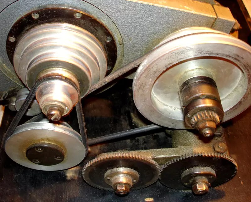 The most common type of torque transmission is belt
 Making a lathe from a drill with your own hands: step by step instructions
The easiest option would be to make a lathe from a drill. Now let's look at step by step what needs to be done for this. We’ll make a reservation right away that such a device will only allow polishing, but not processing at all - there is not enough power for metal turning. We will present more manufacturing videos below, but for now we will consider a device from a drill for woodworking. This will give a general idea, such units are almost identical.
| Illustration | Action to take |
 | To begin with, we saw off a blank from a wooden handle. A handle will subsequently be made from it. |
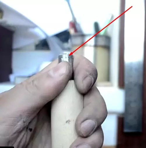 | We drive a sharpened drill into the center of one of the ends. This side will be clamped in the power drill chuck. |
 | We make a frame. In our case, it is wooden. These clamps are needed for rigid fixation of the drill-drive. |
 | Installing the drive. The location of the clamps must be clearly calculated according to the size. |
 | All screws of the clamps are pulled thoroughly. The reliability of fastening, and hence the final result, depends on this. |
 | In the chuck of a fixed electric drill, we install a workpiece with a drill driven into it and stretch the clamps with a special key. |
 | We press on the reverse side with the driven center for reliable two-sided fixation. One-sided fastening of the workpiece will not work. All that can be achieved with this is to break the bearings of the drill. |
 | Thoroughly tighten the fixing nuts. Now the equipment is ready to work. |
 | We turn on the drill at maximum speed. The power button is fixed with a button on the side of the handle. Now the workpiece can be given the desired look with a chisel and a file. |
 | Here we have such a neat pen. If you need to grind a metal cylinder, it should be clamped into a chuck, and drill a small hole on the reverse side of the driven center mount, lubricating it with grease or lithol. The rest of the steps are similar. |
DIY Lathe Modernization: Some Tricks
Drill units are easily upgraded. For example, the bed on which the electric drill is attached is made movable, and the part is statically fixed. Then, by installing different cutters instead of a drill, cone-shaped or other holes are made. A wheel with sandpaper will allow you to evenly sand the surface.
As for the installation of the CNC (numerical program control), it will not be possible to do such work on your own. It involves the replacement of components and mechanisms of the lathe.
Good to know! Working on a CNC machine is no easier than working on a mechanical one. The turner also needs to know everything about the speed of rotation, reading drawings and projects, materials of cutters for various metals.

The nuances of working on homemade structures
As in the operation of each equipment, various sometimes unpleasant situations arise during the operation of home-made lathes. Powerful motor for working with large metal parts, gives sensitive vibrations. This leads to uneven processing of the workpiece - marriage. This is treated by setting the centers (leading and driven) on one axis, or using a cam mechanism (with one leading center).
It is not recommended to install a collector motor as an electric drive - it is better to use an asynchronous one. It eliminates the disadvantage of unplanned over-revving that can cause the workpiece to fly out of the clamps, causing personal injury or property damage.
We offer you to see a few photos of lathes made by the hands of ordinary home craftsmen.

In order to make it easier for the reader to understand the algorithm for manufacturing such units, below is a video of making a lathe with your own hands:
Safety rules when working on a homemade lathe
The main thing, as in any business, is attentiveness and accuracy. This applies to every action, from the strength of the clamping of the workpiece to the slightest movement of the cutter. There are special requirements for clothing. It is forbidden to work in loose-fitting overalls, with dangling sleeves or the bottom of the jacket. If the clothes are just like that, you should fix the jacket on the sleeves and on the bottom with an elastic band. Remember, if the sleeve is wound around a rotating workpiece, you can be left without a hand.

It is important to monitor the condition of the wiring. At the slightest smell of burnt insulation, you need to turn off the voltage and find the source. Cutters are carefully inspected for cracks before starting work. If one is found, the use of the tool is prohibited.
Very important! Under no circumstances should you approach the machine while intoxicated. Even a small dose of alcohol or a hangover reduces attentiveness. According to statistics, 70% of people left without limbs as a result of an injury at work were intoxicated or suffered from a hangover.
Maintenance of a homemade unit: what actions are required
After each use of the machine, it must be swept clean so that no dust and chips remain. After that, all rotating parts are lubricated.
It's all about the money. Metal lathes are very, very expensive things, this applies to even the simplest models.
To make this kind of machine with your own hands is quite within the power of anyone who wants it, so many home and handicraft craftsmen build these devices on their own and very successfully.
The lathe is an ancient apparatus, it is an early device for processing a wide variety of parts from a variety of materials - from metal to wood, etc.
Processing is, first of all, turning surfaces both inside and outside, drilling and boring holes of different diameters, threading, shaping surface relief using knurling.
If we talk about turning metal parts, then industrial turning devices manufactured by different factories are expensive and massive units, which are very difficult to control.
They are in no way related to desktop devices, these are serious industrial units that, in principle, are not suitable for handicraft work. Therefore, a homemade lathe is a great idea for all reasons.

Drawing of a lathe.
You can, for example, make it in the form of a mini version, which will be quite enough for processing both metal parts and blanks from any other materials.
When using homemade mini-machines, there are certain limitations: they are mainly designed to work with round parts, with sections such as axles, handles for tools, wheels, etc.
In mini-machines, parts need to be fixed only in a horizontal position for their rotational movements. Excess material in the course of turning is removed with cutters, which are fixed in the support of the lathe.
Components of a mini metal lathe
The composition of any turning device is traditional, all of the elements listed below are present regardless of how it is made - manually at home or in an industrial way.
The devices consist of the following components:
bed
The main bearing element of the entire structure, giving it rigidity and strength. The bed of a homemade lathe is made from a wooden bar or metal blanks in the form of finished corners.
The main requirement for the frame is the necessary strength, since the design of the machine during the machining process is subjected to strong vibration.
Drive unit
The main element of the part responsible for the power of work. The drive must be chosen very correctly based on the power needed. This is not an easy task and should be carefully considered.
A used drive from a washing machine, a construction mixer, or something else will suffice if you are making a lightweight metalworking machine.
The number of revolutions with such drives is about 1500 rpm, and the power is 200W or a little higher.
- Rear grandma.
This is a special steel plate, to which a steel corner is also welded. It is needed to tightly fix the workpiece to the frame for high-quality processing. - Front grandma.
This is the same part as the tailstock, but unlike the front, it is fixed on the movable frame of the device. - Anterior and posterior centers.
- Caliper.
This is one of the key factors for the working elements of the device, which you can read about below.
How is rotation done?

Lathe device.
Torque is generated in the machine in many ways. You can install the working part on the rotary shaft of the electric motor directly. This approach will save a lot of things: both space and money for spare parts.
Unfortunately, such an arrangement is far from always possible, therefore, the so-called gears are appointed as the main performer of the rotational movement. They are chain, belt and friction.
Each type of transmission has its pros and cons:
Belting
The most budgetary transmission option for a motor with many advantages. The main one is reliability. Making a belt drive is simple: most often, craftsmen take one from other devices.
There is also a drawback - this is its fragility, as the belts wear out quickly. You will have to change them quite often.
Chain and friction transmission
Chain drives are expensive and much more bulky than belt drives. But such a transfer will last much longer, so you will get "strategic" cost savings. The friction drive is exactly in the middle between the belt and chain drives.
The main components of the device
The final quality of the machined part depends on the caliper. Forces, time and all other resources invested in the process can go down the drain without a well-established caliper. This part is located on special "sleds" that move along the frame along the guide vectors.
The movement of the caliper can occur in the following directions:
- Longitudinal movement, in which the working element of the device moves along the part to be joined. This direction is made when turning a circular thread or to remove the surface layer of paint or something else from the workpiece.
- The lateral movement of the caliper is performed perpendicular to the axis of the part. With the help of this movement, holes and recesses are made.
- The tilting movement can be carried out at various angles of inclination, it is used to produce surface recesses of various configurations.
It should be remembered that the caliper, as the most working and moving part of the apparatus, is the most wearable.

Elements of a lathe.
Rapid wear is explained by the action of constant and severe vibration, which results in loosening of fasteners and subsequent backlash, which always affects the quality of turning work in one form or another. Such trouble can be avoided, this requires constant adjustment and adjustment of the caliper.
The caliper can be adjusted in different ways. If the backlash is adjustable, then it is eliminated with a screw. Gaps can be eliminated with the help of special inserts between the carriage and the guides.
The gaps appear when the screw is worn, which controls the longitudinal and transverse movements in the planes. The seals can also wear out. In this case, they are washed and lubricated until completely impregnated with engine oil. Sometimes they just need to be replaced with new ones.
Stages of assembling a lathe
The power level of the motor must be calculated depending on the planned work - the dimensions of the metal parts with which you are going to work on your new unit.
If your plans are to work with small parts, a motor with a power of about 1 kW will be enough. Such motors are found on sewing machines or other household electrical appliances. If your future parts are larger, choose a motor with a power of 1.5 to 2.0 kW.
The power also depends on the material you are going to work with. If, for example, your material is wood, then home-made wood lathes with your own hands, including a home-made cutter for a wood lathe, will not require much power.
The most important issue is the reliable isolation of all electrical components. The best option would be to consult a specialist. Confidence in the safety of the device and the professional reliability of the design will not hurt you: after all, you are going to work with electricity and metals. And they don't joke around.
We make a machine from a drill
The drill will look great as a drive to the lathe.
With this elegant solution, you will save a lot of money and make your life much easier, because it has a number of great advantages:
- Modularity of the device: it is simply assembled and disassembled. The drill is detached from the bed without any difficulty and reattached.
- Such a model is very transportable, you can work with it everywhere - even in the country, even in the garage.
- Significant cost savings: no need to purchase additional replacement tips or belt drive.
To assemble a device from a drill, you will need almost the same parts as for a conventional device. Only two things will not be needed: an electric motor and a headstock, and these are the most important and most expensive structural elements.
Since the machine is light and compact, there is no need to build a stable bed, a workbench or table will be enough. The drill is fixed with a clamp and a clamp.

The design and dimensions of the lathe.
The expansion of the functions of a turning device from a drill can be done using additional nozzles and other devices. You can make great homemade woodworking machines.
There are, of course, downsides. On the device from a drill, you will not be able to process large parts. You can try to improve the model in this direction. For example, add a belt drive and to increase the number of revolutions.
But the game is not worth the candle: it will lose its main advantages in the form of simplicity and lightness. Thus, a home-made apparatus from a drill makes sense only in cases where work is underway with medium-sized parts.
A lathe from a drill is capable of much: it can not only process parts. But also work with paints - apply them to the workpiece during its rotation. This is a homemade woodworking machine.
Winding wire on a transformer, applying various kinds of notches on the surface of parts are just some examples of using a multifunctional machine from a drill and a turning tool for metal.
And now the simplest machine
Today, the network has a huge number of drawings, instructions and videos on the topic “how to make a homemade lathe”, with the help of which independent work on the manufacture of a lathe is quite real and almost everyone can do it.
You can, of course, aim at a mini-machine with program control. And you can stop at the simplest option, which will work perfectly at low cost on a variety of details of various configurations.
Wooden racks are attached to the frame with bolts. The bed must be reliable, therefore it is made of steel corners. In extreme cases, it can be made from bars.

Wood lathe device.
The cutting element is fixed on the knot from the handpiece, it will move along it. A sheet of metal should be tightly fixed on the moving surface to protect the structure from deformation. In addition, it will help to position the metal turning tool exactly to the part to be machined.
For the manufacture of the headstock and tailstock, suitable metal cylinders with the appropriate diameter are selected. They are placed in bearing assemblies, which are pre-placed in wooden racks.
The rotational movement is transmitted through the front center, combined with the motor using a belt drive. The part is fixed between the front and rear sections and processed with a cutter from a handpiece.
There are no problems with the search and selection of an electric motor for a mini lathe.
We already wrote that a small power motor can be found on any household electrical device, any used household appliance is quite suitable for this task. As a drive, you can use grinders or drills.
Safety
Since we are talking about working with metals, the requirements for complying with safety regulations will be clear and tough, from which you cannot escape. The first step is to check the performance of the new machine immediately after its manufacture.
How to check the performance of the machine: the spindle should rotate without the slightest difficulty. It is necessary to measure the coincidence of the axis of rotation of the parts in the machine with the center of symmetry of the same part. The common axis should be visible at the front and rear centers.

Elements of the design of the machine for turning.
The electric motor is always covered with a special casing that protects the motor from dirt and metal particles, as well as the machine operator himself. If your device is made from a drill, no casing is needed.
If you decide to equip your homemade lathe with a powerful motor, be sure to test in your home network to see if it is enough for your powerful motor. In general, it is better to adhere to established traditions and use old acquaintances - electric motors from household appliances.
Making a homemade lathe is a great and elegant solution from all points of view. Ease of execution, cost savings, efficient processing of parts - all this is about homemade lathes.
Thanks to lathes for metal, a person gets the opportunity to make some parts on his own. It is not always possible to buy a part for a car or special equipment.
And most often, not because there is not enough money, just when it comes to old Soviet special equipment or automotive products, many models are no longer produced. But nevertheless, this does not deprive the user of the opportunity to use them. Do-it-yourself metal lathes make it possible to do everything you need at home.
Why buy a metal lathe when you can make one yourself. It's not that difficult, and all you need is the availability of drawings, a little patience and old electrical engineering. Let's look at how to make such equipment yourself.
TV 16 screw-cutting
The principle of operation of any lathe is the processing of a part during its rotation. Thus, the cutter inserted into the plane of rotation, upon contact with the workpiece, will remove unnecessary elements. Such equipment is amenable to automation, so that the operator is able to:
- Perform longitudinal turning of a cylindrical workpiece with a smooth or stepped surface;
- Process ledges or grooves in the future part;
- To perform a groove of external or internal surfaces of a conical shape;
- Carry out threading, both internal and external, using a cutter or drill;
- Reaming or countersinking holes in a metal workpiece;
- Cut off excess parts or cut grooves;
- Perform knurling of the corrugated surface of the workpiece.
The main purpose in the use of a metal lathe is the processing of shafts, bushings or discs. Thus, a person gets the opportunity to make an axis, a flywheel, sprockets, various liners, etc. from the workpiece. Also on a universal lathe, you can perform the processing of body parts.
There is a certain classification of turning equipment. They are divided as follows
- On a turning basis. There are as many as 9 subgroups when dividing equipment in this way.
- Size range. Classification is performed depending on the diameter of the workpiece that you will process.
- The level of specialization. Depending on the profile of the work performed and the capabilities of the equipment.
- The accuracy class of the machine.
The most famous and used for the home workshop are screw-cutting lathes.
They gained their popularity back in the Soviet years, when they taught the younger generation how to process metal parts. The main purpose of the machines of this group is just the training of specialists to work with more complex equipment.
This implies ease of operation and mastering the machine. As well as a high level of safety and minimum safety requirements for the operator.
Now such equipment is produced in a modern way. Such models have increased functionality, designed for the operation of the enterprise, therefore, it is not advisable to install such equipment at home.
It will be expensive - there is no point in overpaying for functionality that you will never use in your life.
The old TV-16 machines, which were equipped in almost all labor rooms and production workshops for training specialists in educational institutions, are ideal for home use. The problem is that getting such equipment even from a reservation is very problematic.
You can, of course, buy from the photo on Avito, but you buy it from your hands, and it’s not a fact that the machine will last you a long time after the old owner.
It is best to do it yourself, especially since there is nothing complicated about it. You will need tools and materials that are not a problem to get. Having built a metal machine with your own hands, you will not only receive equipment for working with blanks, but also save a lot of money on the purchase and services of turners.
How the machine works - important structural elements

Construction scheme.
Any equipment must have a basis, without which it will not function. In a screw-cutting lathe, such structural elements are:
- Front and rear headstock;
- The bed or frame, which is the basis for the equipment;
- Electric drive;
- Control centers - driven and leading parts of the machine;
- A handpiece where the operator will rest the cutting tools for processing the part.
This can also include grounding and a protective screen. The first will ensure you are safe from electric shock, and the second will protect you from getting shavings in your face.
The unit will be installed on a special steel. If you make this equipment yourself, such a bed is a frame.
Advice: it is best to choose a high-quality and durable metal for the base. The stronger the frame, the more securely the equipment will be fixed. This eliminates the rattling of the screw-cutting unit.
A tailstock will be installed along the frame. This device is mobile. The front is immovable. It is connected by a belt drive to the drive, which makes the workpiece move.
For screw-cutting equipment, the center, which is the leading one, will connect the engine together with the transmission device for rotation. The drive itself is best installed on the frame. At home, strong metal corners and profiles are best suited to create a bed. You will also need a few pieces of wood to set up as a stand to dampen the vibrations of the equipment.
It is important not so much what you will use, but the stability of the finished frame. A motor is suitable as an electric drive, it is best that it be from under a high-power washing machine.
The entire installation will be powered by 380V, so you will definitely need to run wires to the garage that can meet this requirement. You will also need an old table, which will be a stand for the machine. It is best to choose a sturdy table made of wood or metal.
The transmission of revolutions to the shafts can be carried out using a chain, friction or belt drive. A belt is best suited because it is the most efficient, simple and reliable type.
Do-it-yourself design features of a screw-cutting lathe

General view of a homemade machine.
It is not difficult to make a homemade lathe at home. The main thing is to follow a number of rules that will help you do this. The first step is to replace the slaves and the leading centers of the equipment on the same axis. In this way, the user removes vibrations that may occur during the processing of metal workpieces.
Important! When using equipment with one leading center, you need to install a special chuck or faceplate.
Thanks to these elements, the user will be able to fix the part for further processing with cutting tools.
Important! In no case should engines be installed as a collector-type electric drive.
If such an assembly is not provided with an additional counter-load, the torque will be too strong. You won't be able to grind anything at such speeds. In addition, the part may simply fly out of the clamps, which will not provide sufficient clamping force.
Thus, it is possible not only to damage the workpiece itself, but also to suffer well if it hits a person. For this purpose, use an asynchronous motor. The essence of his work is that even with an increase or decrease in the load, the speed transmitted to the shafts will not change.
Such a unit will allow the operator to process parts of the following dimensions:
- Thickness - 10 cm;
- Width - up to 70 cm.
The tailstock is a unique structural part of the machine where the driven center is mounted. It can be fixed or dynamic. An elementary bolt is used to move it. Twisting or untwisting, the headstock will move in the direction desired by the operator.
Before installing such a bolt, lubricate it with machine oil for better and more comfortable sliding. Only then can it be inserted into the thread, which is designed to move the tailstock of the installation.
To work on creating a machine from improvised means, you will need a few simple tools that every person can find
- Electric welding;
- Bulgarian;
- Grinding machine;
- Drill with a set of drills;
- Spanners;
- Measurement tools - vernier caliper along with a tape measure or ruler;
- Pen, pencil or marker for marking.
The first step is to think over the drawing, and then proceed with the installation.
Design of the future product
Drawings with dimensions.
- Length - up to 115 cm;
- Width up to 62 cm;
- The height of the axis of the equipment is 18 cm.
Important! These dimensions should not be exceeded in the manufacture of the machine in artisanal conditions. This can lead to a violation of its geometry during operation.
When you draw up a project, draw all the details, or download drawings with dimensions from the Internet and work according to the finished plan. If you try to keep everything in your head, you will definitely make a mistake that will ruin all the equipment.
You will build on the accuracy of the project and the drawing of future equipment not only in the process of work, but also during the purchase of the necessary consumables.
We create a lathe based on an electric motor
Now let's look at the assembly sequence of a home metal lathe.
- We make a frame. We, according to the drawing, process the channel or profile corner. We measure and cut off unnecessary. Using welding, we securely weld the frame so that we get an even rectangle.
- Installation of rails and attendants. A rail with a tailstock will be mounted on it, on one side. And weld the headstock on the other.
- Drive installation. On the back of the frame, an electric motor is installed. It is placed as close as possible to the headstock, so that with the help of shafts and a belt it is possible to practically ensure the possibility of transmitting rotation to the working part.
- Installing a handbrake. When the previous stage is completed, we put the tool stand. It is not welded, but is made movable with nuts and bolts. The movement of the hand rest should be carried out in a direction perpendicular to the workpiece.
- Installing the protective cover and putting the belt on the transmission shafts.
- Connecting the motor to the network and grounding.
- Visual inspection for correct assembly and test run.
Tip: To better understand how to make a machine - see video below.
You can be congratulated - the home lathe is ready. Now you can effortlessly produce any necessary metal parts for special equipment or a car. Also, you can now independently repair certain parts of a vehicle or household tool.