Before installation and installation of any fire extinguishing equipment, its layout is preliminarily designed by a specialist. This also applies to gas fire extinguishing. Competently and correctly carried out work on the drafting of a gas fire extinguishing system will avoid many problems with the subsequent reinstallation of the complex, emergencies and other troubles.
How gas fire extinguishing is designed - general provisions and principles
The preparation of the project begins with the study of the initial data on the object of protection. The specialist takes into account such parameters as:
- dimensions of the premises;
- the location of the floors, their design;
- placement of engineering communications;
- the presence and size (area) of openings in the building envelope, which are constantly open;
- values of the maximum allowable pressure in the premises;
- microclimatic parameters of the premises where the AUGP components will be placed;
- fire hazard of premises, fire class according to the State Standard for substances and materials stored there;
- features (if any) of the HVAC system (heating, ventilation, air conditioning);
- availability and characteristics of technological equipment in the premises;
- the number of permanently present people in the premises;
- features of evacuation routes and exits.
The amount of data that needs to be known and taken into account when designing is significant. Based on the information collected, the designer calculates the gas fire extinguishing system.
As a result, the AUGP parameters suitable for a particular object will be selected:
- the required amount of gas fire extinguishing agent;
- optimal duration of GOTV supply;
- required pipeline diameter, type and number of nozzles for installation;
- maximum overpressure when supplying a fire extinguishing agent;
- the number of reserve modules (cylinders) with GOTV;
- type and number of fire detectors (sensors).
The design of gas PT installations is carried out on the basis of fire safety standards (NPB No. 22-96).
Stages of designing gas fire extinguishing at facilities
Any gas fire extinguishing project begins with the receipt of an assignment from the customer for the performance of work, and then - the collection and analysis of data on the object.
The next plan of action is as follows:
- Determining the type of AUGP (modular, mobile, stationary).
- Engineering calculations.
- Development and execution of drawings of the gas fire extinguishing installation project.
- Preparation of specifications for materials and equipment.
- Development of specific tasks for further installation of AUGP.
According to current regulations, when designing an AUGP, some nuances must be taken into account:
- organization of openings to relieve excess pressure;
- integration of gas fire extinguishing with other building systems;
- planning for effective gas removal from the premises after using AUGP, etc.
Calculations require the designer to have special knowledge, permits and licenses to carry out this kind of work.
We are ready to provide all this, as well as measures for the installation and further service of gas fire extinguishing systems, to our customers.
The design of gas fire extinguishing systems is a rather complex intellectual process, the result of which is a workable system that allows you to reliably, timely and effectively protect an object from fire. This article discusses and analyzesproblems that arise in the design of automaticgas fire extinguishing installations. Possibleperformance of these systems and their effectiveness, as well as considerationpossible variants of the optimal constructionautomatic gas fire extinguishing systems. Analysisof these systems is produced in full compliance with theaccording to the code of rules SP 5.13130.2009 and other norms validSNiP, NPB, GOST and Federal Laws and OrdersRussian Federation on automatic fire extinguishing installations.
Chief Engineer project of ASPT Spetsavtomatika LLC
V.P. Sokolov
Today, one of the most effective means of extinguishing fires in premises subject to protection by automatic fire extinguishing installations AUPT in accordance with the requirements of SP 5.13130.2009 Appendix "A" are automatic gas fire extinguishing installations. The type of automatic extinguishing installation, the method of extinguishing, the type of fire extinguishing agents, the type of equipment for fire automatics installations is determined by the design organization, depending on the technological, structural and space-planning features of the protected buildings and premises, taking into account the requirements of this list (see clause A.3. ).
The use of systems where the fire extinguishing agent is automatically or remotely in the manual start mode is supplied to the protected room in the event of a fire, is especially justified when protecting expensive equipment, archival materials or valuables. Automatic fire extinguishing installations make it possible to eliminate at an early stage the ignition of solid, liquid and gaseous substances, as well as energized electrical equipment. This method of extinguishing can be volumetric - when creating a fire extinguishing concentration throughout the volume of the protected premises or local - if the fire extinguishing concentration is created around the protected device (for example, a separate unit or unit of technological equipment).
When choosing the optimal option for controlling automatic fire extinguishing installations and choosing a fire extinguishing agent, as a rule, they are guided by the norms, technical requirements, features and functionality of the protected objects. When properly selected, gas fire extinguishing agents practically do not cause damage to the protected object, the equipment located in it with any production and technical purpose, as well as the health of permanently staying personnel working in the protected premises. The unique ability of gas to penetrate through cracks into the most inaccessible places and effectively affect the source of fire has become the most widespread in the use of gas fire extinguishing agents in automatic gas fire extinguishing installations in all areas of human activity.
That is why automatic gas fire extinguishing installations are used to protect: data processing centers (DPC), server, telephone communication centers, archives, libraries, museum storerooms, bank vaults, etc.
Consider the types of fire extinguishing agents most commonly used in automatic gas fire extinguishing systems:
Freon 125 (C 2 F 5 H) standard volumetric fire extinguishing concentration according to N-heptane GOST 25823 is equal to - 9.8% of the volume (trade name HFC-125);
Freon 227ea (C3F7H) standard volumetric fire extinguishing concentration according to N-heptane GOST 25823 is equal to - 7.2% of the volume (trade name FM-200);
Freon 318Ts (C 4 F 8) standard volumetric fire extinguishing concentration according to N-heptane GOST 25823 is equal to - 7.8% of the volume (trade name HFC-318C);
Freon FK-5-1-12 (CF 3 CF 2 C (O) CF (CF 3) 2) standard volumetric fire extinguishing concentration according to N-heptane GOST 25823 is - 4.2% by volume (brand name Novec 1230);
Carbon dioxide (CO 2) standard volumetric fire extinguishing concentration according to N-heptane GOST 25823 is equal to - 34.9% of the volume (can be used without permanent stay of people in the protected room).
We will not analyze the properties of gases and their principles of impact on fire in the fire. Our task will be the practical use of these gases in automatic gas fire extinguishing installations, the ideology of building these systems in the design process, the issues of calculating the mass of gas to ensure the standard concentration in the volume of the protected room and determining the diameters of the pipes of the supply and distribution pipelines, as well as calculating the area of nozzle outlets .
In gas fire extinguishing projects, when filling out the stamp of the drawing, on the title pages and in the explanatory note, we use the term automatic gas fire extinguishing installation. In fact, this term is not entirely correct and it would be more correct to use the term automated gas fire extinguishing installation.
Why is that! We look at the list of terms in SP 5.13130.2009.
3. Terms and definitions.
3.1 Automatic start of fire extinguishing installation: start-up of the installation from its technical means without human intervention.
3.2 Automatic fire extinguishing installation (AUP): a fire extinguishing installation that automatically operates when the controlled fire factor (factors) exceeds the established threshold values in the protected area.
In the theory of automatic control and regulation, there is a separation of the terms automatic control and automated control.
Automatic systems is a complex of software and hardware tools and devices that work without human intervention. An automatic system does not have to be a complex set of devices for managing engineering systems and technological processes. It can be one automatic device that performs the specified functions according to a predetermined program without human intervention.
Automated systems is a complex of devices that convert information into signals and transmit these signals over a distance via a communication channel for measurement, signaling and control without human participation or with his participation on no more than one transmission side. Automated systems are a combination of two automatic control systems and a manual (remote) control system.
Consider the composition of automatic and automated control systems for active fire protection:
Means for obtaining information - information gathering devices.
Means for information transfer - communication lines (channels).
Means for receiving, processing information and issuing control signals of the lower level - local reception electrotechnical devices,devices and stations of control and management.
Means for the use of information- automatic regulators andactuators and warning devices for various purposes.
Means for displaying and processing information, as well as top-level automated control - central control oroperator workstation.
Automatic gas fire extinguishing installation AUGPT includes three start modes:
- automatic (start is carried out from automatic fire detectors);
- remote (launch is carried out from a manual fire detector located at the door to the protected room or guard post);
- local (from a mechanical manual start device located on the launch module “cylinder” with a fire extinguishing agent or next to the fire extinguishing module for liquid carbon dioxide MPZHUU structurally made in the form of an isothermal container).
Remote and local start modes are performed only with human intervention. So the correct decoding of AUGPT will be the term « Automated gas fire extinguishing installation".
Recently, when coordinating and approving a gas fire extinguishing project for work, the Customer requires that the inertia of the fire extinguishing installation be indicated, and not just the estimated delay time for gas release to evacuate personnel from the protected premises.
3.34 The inertia of the fire extinguishing installation: time from the moment the controlled fire factor reaches the threshold of the sensing element of the fire detector, sprinkler or stimulus until the start of the supply of fire extinguishing agent to the protected area.
Note- For fire extinguishing installations, which provide for a time delay for the release of a fire extinguishing agent in order to safely evacuate people from the protected premises and (or) to control process equipment, this time is included in the inertia of the AFS.
8.7 Time characteristics (see SP 5.13130.2009).
8.7.1 The installation must ensure the delay in the release of GFEA into the protected room during automatic and remote start for the time required to evacuate people from the room, turn off ventilation (air conditioning, etc.), close dampers (fire dampers, etc.), but not less than 10 sec. from the moment the evacuation warning devices are turned on in the room.
8.7.2 The unit must provide inertia (actuation time without taking into account the delay time for the release of GFFS) no more than 15 seconds.
The delay time for the release of a gas fire extinguishing agent (GOTV) into the protected premises is set by programming the algorithm of the station that controls the gas fire extinguishing. The time required for the evacuation of people from the premises is determined by calculation using a special method. The time interval of delays for the evacuation of people from the protected premises can be from 10 seconds. up to 1 min. and more. The gas release delay time depends on the dimensions of the protected premises, the complexity of the technological processes in it, the functional features of the installed equipment and the technical purpose, both of individual premises and industrial facilities.
The second part of the inertial delay of the gas fire extinguishing installation in time is the product of the hydraulic calculation of the supply and distribution pipeline with nozzles. The longer and more complex the main pipeline to the nozzle, the more important the inertia of the gas fire extinguishing installation. In fact, compared with the time delay required to evacuate people from the protected premises, this value is not so large.
The inertia time of the installation (the beginning of the outflow of gas through the first nozzle after opening the shut-off valves) is min 0.14 sec. and max. 1.2 sec. This result was obtained from the analysis of about a hundred hydraulic calculations of varying complexity and with different gas compositions, both freons and carbon dioxide located in cylinders (modules).
Thus the term "Inertia of the gas fire extinguishing installation" is made up of two components:
Gas release delay time for safe evacuation of people from the premises;
The time of technological inertia of the operation of the installation itself during the production of GOTV.
It is necessary to separately consider the inertia of the gas fire extinguishing installation with carbon dioxide based on the reservoir of the isothermal fire-fighting MPZHU "Volcano" with different volumes of the vessel used. A structurally unified series is formed by vessels with a capacity of 3; 5; ten; 16; 25; 28; 30m3 for working pressure 2.2MPa and 3.3MPa. To complete these vessels with shut-off and starting devices (LPU), depending on the volume, three types of shut-off valves are used with nominal diameters of the outlet opening of 100, 150 and 200 mm. A ball valve or a butterfly valve is used as an actuator in the shut-off and starting device. As a drive, a pneumatic drive with a working pressure on the piston of 8-10 atmospheres is used.
Unlike modular installations, where the electric start of the main shut-off and starting device is carried out almost instantly, even with the subsequent pneumatic start of the remaining modules in the battery (see Fig-1), the butterfly valve or ball valve opens and closes with a small time delay, which can be 1-3 sec. depending on the equipment manufacturer. In addition, the opening and closing of this LSD equipment in time due to the design features of the shut-off valves has a far from linear relationship (see Fig-2).
The figure (Fig-1 and Fig-2) shows a graph in which on one axis are the values of the average consumption of carbon dioxide, and on the other axis are the values of time. The area under the curve within the target time determines the calculated amount of carbon dioxide.
Average consumption of carbon dioxide Q m, kg/s, is determined by the formula
where: m- estimated amount of carbon dioxide ("Mg" according to SP 5.13130.2009), kg;
t- normative time of carbon dioxide supply, s.
with modular carbon dioxide. 
Fig-1.
1-
to - opening time of the locking-starting device (LPU).
tx – the end time of CO2 gas outflow through the ZPU.
Automated gas fire extinguishing installation
with carbon dioxide on the basis of the isothermal tank MPZHU "Volcano".
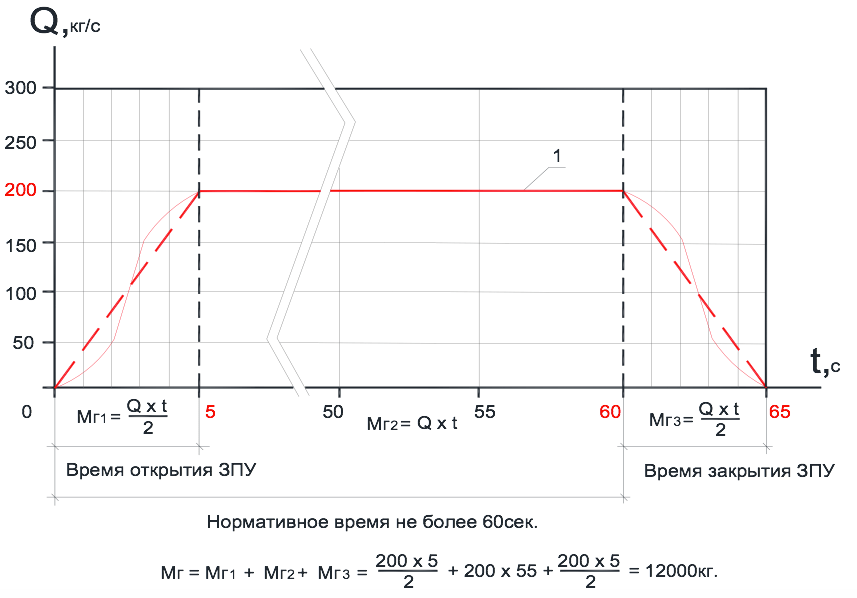 Fig-2.
1- curve that determines the consumption of carbon dioxide over time through the ZPU.
The storage of the main and reserve stock of carbon dioxide in isothermal tanks can be carried out in two different separate tanks or together in one. In the second case, it becomes necessary to close the shut-off and starting device after the release of the main stock from the isothermal tank during an emergency fire extinguishing situation in the protected room. This process is shown in the figure as an example (see Fig-2).
The use of the isothermal tank MPZHU "Volcano" as a centralized fire extinguishing station in several directions implies the use of a lock-start device (LPU) with an open-close function to cut off the required (calculated) amount of fire extinguishing agent for each direction of gas fire extinguishing.
The presence of a large distribution network of the gas fire extinguishing pipeline does not mean that the outflow of gas from the nozzle will not begin before the LPU is fully opened, therefore, the time of opening the exhaust valve cannot be included in the technological inertia of the installation during the release of GFFS.
A large number of automated gas fire extinguishing installations are used at enterprises with various technical industries to protect process equipment and installations, both with normal operating temperatures and with a high level of operating temperatures on the working surfaces of the units, for example:
Gas compressor units of compressor stations, subdivided by type
drive engine for gas turbine, gas engine and electric;
High pressure compressor stations driven by an electric motor;
Generator sets with gas turbine, gas engine and diesel
drives;
Production process equipment for compression and
preparation of gas and condensate at oil and gas condensate fields, etc.
For example, the working surface of the casings of a gas turbine drive for an electric generator in certain situations can reach sufficiently high heating temperatures that exceed the autoignition temperature of some substances. In the event of an emergency, fire, on this process equipment and further elimination of this fire using an automatic gas fire extinguishing system, there is always a possibility of relapse, re-ignition when hot surfaces come into contact with natural gas or turbine oil, which is used in lubrication systems.
For equipment with hot working surfaces in 1986. VNIIPO of the Ministry of Internal Affairs of the USSR for the Ministry of Gas Industry of the USSR developed the document "Fire protection of gas pumping units of compressor stations of main gas pipelines" (Generalized recommendations). Where it is proposed to use individual and combined fire extinguishing installations to extinguish such objects. Combined fire extinguishing installations imply two stages of putting fire extinguishing agents into action. The list of combinations of fire extinguishing agents is available in the generalized training manual. In this article, we consider only combined gas fire extinguishing installations "gas plus gas". The first stage of gas fire extinguishing of the facility complies with the norms and requirements of SP 5.13130.2009, and the second stage (extinguishing) eliminates the possibility of re-ignition. The method for calculating the mass of gas for the second stage is given in detail in the generalized recommendations, see the section "Automatic gas fire extinguishing installations".
To start the gas fire extinguishing system of the first stage in technical installations without the presence of people, the inertia of the gas fire extinguishing installation (gas start delay) must correspond to the time required to stop the operation of the technical means and turn off the air cooling equipment. The delay is provided in order to prevent the entrainment of the gas fire extinguishing agent.
For the second stage gas fire extinguishing system, a passive method is recommended to prevent the recurrence of re-ignition. The passive method implies the inerting of the protected room for a time sufficient for the natural cooling of the heated equipment. The time for supplying a fire extinguishing agent to the protected area is calculated and, depending on the technological equipment, can be 15-20 minutes or more. The operation of the second stage of the gas fire extinguishing system is carried out in the mode of maintaining a given fire extinguishing concentration. The second stage of gas fire extinguishing is switched on immediately after the completion of the first stage. The first and second stages of gas fire extinguishing for the supply of fire extinguishing agent must have their own separate piping and a separate hydraulic calculation of the distribution pipeline with nozzles. The time intervals between which the cylinders of the second stage of fire extinguishing are opened and the supply of fire extinguishing agent is determined by calculations.
As a rule, carbon dioxide CO 2 is used to extinguish the equipment described above, but freons 125, 227ea and others can also be used. Everything is determined by the value of the protected equipment, the requirements for the effect of the selected fire extinguishing agent (gas) on the equipment, as well as the effectiveness of the extinguishing. This issue lies entirely within the competence of specialists involved in the design of gas fire extinguishing systems in this area.
The automation control scheme of such an automated combined gas fire extinguishing installation is quite complex and requires a very flexible control and management logic from the control station. It is necessary to carefully approach the choice of electrical equipment, that is, gas fire extinguishing control devices.
Now we need to consider general issues on the placement and installation of gas fire extinguishing equipment.
8.9 Pipelines (see SP 5.13130.2009).
8.9.8 The distribution piping system should generally be symmetrical.
8.9.9 The internal volume of pipelines must not exceed 80% of the volume of the liquid phase of the calculated amount of GFFS at a temperature of 20°C.
8.11 Nozzles (see SP 5.13130.2009).
8.11.2 Nozzles should be placed in the protected room, taking into account its geometry, and ensure the distribution of GFEA throughout the volume of the room with a concentration not lower than the standard one.
8.11.4 The difference in DHW flow rates between two extreme nozzles on one distribution pipeline should not exceed 20%.
8.11.6 In one room (protected volume), nozzles of only one standard size should be used.
3. Terms and definitions (see SP 5.13130.2009).
3.78 Distribution pipeline: pipeline on which sprinklers, sprayers or nozzles are mounted.
3.11 Distribution pipeline branch: section of a distribution pipeline row located on one side of the supply pipeline.
3.87 Row of distribution pipeline: a set of two branches of a distribution pipeline located along the same line on both sides of the supply pipeline.
Increasingly, when coordinating design documentation for gas fire extinguishing, one has to deal with different interpretations of some terms and definitions. Especially if the axonometric scheme of piping for hydraulic calculations is sent by the Customer himself. In many organizations, gas fire extinguishing systems and water fire extinguishing are handled by the same specialists. Consider two schemes for distributing gas fire extinguishing pipes, see Fig-3 and Fig-4. The comb type scheme is mainly used in water fire extinguishing systems. Both schemes shown in the figures are also used in the gas fire extinguishing system. There is only a limitation for the "comb" scheme, it can only be used for extinguishing with carbon dioxide (carbon dioxide). The normative time for the release of carbon dioxide into the protected room is no more than 60 seconds, and it does not matter if it is a modular or centralized gas fire extinguishing installation.
The time for filling the entire pipeline with carbon dioxide, depending on its length and the diameters of the tubes, can be 2-4 seconds, and then the entire pipeline system up to the distribution pipelines on which the nozzles are located, turns, as in the water fire extinguishing system, into a “supply pipeline”. Subject to all the rules of hydraulic calculation and the correct selection of the internal diameters of the pipes, the requirement will be met in which the difference in the DHW flow rates between the two extreme nozzles on one distribution pipeline or between the two extreme nozzles on the two extreme rows of the supply pipeline, for example, rows 1 and 4, will not exceed twenty%. (See copy of paragraph 8.11.4). The working pressure of carbon dioxide at the outlet in front of the nozzles will be approximately the same, which will ensure uniform consumption of the GOTV fire extinguishing agent through all nozzles in time and the creation of a standard gas concentration at any point in the volume of the protected room after 60 seconds. since the launch of the gas fire extinguishing installation.
Another thing is the variety of fire extinguishing agent - freons. The standard time for the release of freon into the protected room for modular fire extinguishing is no more than 10 seconds, and for a centralized installation no more than 15 seconds. etc. (see SP 5.13130.2009).
firefightingaccording to the "comb" type scheme.

FIG. 3.
As the hydraulic calculation with freon gas (125, 227ea, 318Ts and FK-5-1-12) shows, the main requirement of the set of rules is not met for the axonometric layout of the comb-type pipeline, which is to ensure a uniform flow of fire extinguishing agent through all nozzles and ensure the distribution of fire extinguishing agent over the entire volume of the protected premises with a concentration not lower than the standard (see the copy of paragraph 8.11.2 and paragraph 8.11.4). The difference in the flow rate of the freon family DHW through nozzles between the first and last rows can reach 65% instead of the allowable 20%, especially if the number of rows on the supply pipeline reaches 7 pcs. and more. Obtaining such results for a gas of the freon family can be explained by the physics of the process: the transience of the ongoing process in time, so that each subsequent row takes part of the gas onto itself, a gradual increase in the length of the pipeline from row to row, the dynamics of resistance to gas movement through the pipeline. This means that the first row with nozzles on the supply pipeline is in more favorable operating conditions than the last row.
The rule states that the difference in DHW flow rates between two extreme nozzles on the same distribution pipeline should not exceed 20% and nothing is said about the difference in flow rate between rows on the supply pipeline. Although another rule states that the nozzles must be placed in the protected room, taking into account its geometry and ensure the distribution of GOV throughout the volume of the room with a concentration not lower than the standard one.
Gas installation piping plan
fire extinguishing systems in a symmetrical pattern.

FIG-4.
How to understand the requirement of the code of practice, the distribution piping system, as a rule, must be symmetrical (see copy 8.9.8). The “comb” type piping system of the gas fire extinguishing installation also has symmetry with respect to the supply pipeline and at the same time does not provide the same freon gas flow rate through nozzles throughout the volume of the protected room.
Figure-4 shows the piping system for a gas fire extinguishing installation according to all symmetry rules. This is determined by three signs: the distance from the gas module to any nozzle has the same length, the diameters of the pipes to any nozzle are identical, the number of bends and their direction are similar. The difference in gas flow rates between any nozzles is practically zero. If, according to the architecture of the protected premises, it is necessary to lengthen or move a distribution pipeline with a nozzle to the side, the difference in flow rates between all nozzles will never exceed 20%.
Another problem for gas fire extinguishing installations is the high height of the protected premises from 5 m or more (see Fig-5).
Axonometric diagram of the piping of the gas fire extinguishing installationin a room of the same volume with a high ceiling height.

Fig-5.
This problem arises when protecting industrial enterprises, where the production workshops to be protected can have ceilings up to 12 meters high, specialized archive buildings with ceilings reaching heights of 8 meters and above, hangars for storing and servicing various special equipment, gas and oil products pumping stations, etc. .d. The generally accepted maximum installation height of the nozzle relative to the floor in the protected room, which is widely used in gas fire extinguishing installations, as a rule, is no more than 4.5 meters. It is at this height that the developer of this equipment checks the operation of his nozzle to ensure that its parameters comply with the requirements of SP 5.13130.2009, as well as the requirements of other regulatory documents of the Russian Federation on fire safety.
With a high height of the production facility, for example 8.5 meters, the process equipment itself will definitely be located at the bottom of the production site. In case of volumetric extinguishing with a gas fire extinguishing installation in accordance with the rules of SP 5.13130.2009, nozzles must be located on the ceiling of the protected room, at a height of not more than 0.5 meters from the ceiling surface in strict accordance with their technical parameters. It is clear that the height of the production room of 8.5 meters does not meet the technical characteristics of the nozzle. Nozzles should be placed in the protected room, taking into account its geometry and ensure the distribution of GFEA throughout the volume of the room with a concentration not lower than the standard one (see paragraph 8.11.2 from SP 5.13130.2009). The question is how long it will take to equalize the standard concentration of gas throughout the volume of the protected room with high ceilings, and what rules can regulate this. One solution to this issue seems to be a conditional division of the total volume of the protected room in height into two (three) equal parts, and along the boundaries of these volumes, every 4 meters down the wall, symmetrically install additional nozzles (see Fig-5). Additionally installed nozzles allow you to quickly fill the volume of the protected room with a fire extinguishing agent with the provision of a standard gas concentration, and, more importantly, ensure a quick supply of a fire extinguishing agent to the process equipment at the production site.
According to the given piping layout (see Fig-5), it is most convenient to have nozzles with 360° GFEA spraying on the ceiling, and 180° GFFS side spray nozzles on the walls of the same standard size and equal to the estimated area of the spray holes. As the rule says, nozzles of only one standard size should be used in one room (protected volume) (see copy of clause 8.11.6). True, the definition of the term nozzles of one standard size is not given in SP 5.13130.2009.
For the hydraulic calculation of the distribution pipeline with nozzles and the calculation of the mass of the required amount of gas fire extinguishing agent to create a standard fire extinguishing concentration in the protected volume, modern computer programs are used. Previously, this calculation was carried out manually using special approved methods. This was a complex and time-consuming action, and the result obtained had a rather large error. To obtain reliable results of the hydraulic calculation of piping, a large experience of a person involved in the calculations of gas fire extinguishing systems was required. With the advent of computer and training programs, hydraulic calculations have become available to a wide range of specialists working in this field. The computer program "Vector", one of the few programs that allows you to optimally solve all kinds of complex problems in the field of gas fire extinguishing systems with minimal loss of time for calculations. To confirm the reliability of the calculation results, the verification of hydraulic calculations using the computer program "Vector" was carried out and a positive Expert opinion No. 40/20-2016 dated 31.03.2016 was received. Academy of the State Fire Service of the Ministry of Emergency Situations of Russia for the use of the program of hydraulic calculations "Vector" in gas fire extinguishing installations with the following fire extinguishing agents: Freon 125, Freon 227ea, Freon 318Ts, FK-5-1-12 and CO2 (carbon dioxide) produced by ASPT Spetsavtomatika LLC.
The computer program for hydraulic calculations "Vector" frees the designer from routine work. It contains all the norms and rules of SP 5.13130.2009, it is within the framework of these restrictions that calculations are performed. A person inserts into the program only his initial data for calculation and makes changes if he is not satisfied with the result.
Finally I would like to say that we are proud that, according to many experts, ASPT Spetsavtomatika LLC is one of the leading Russian manufacturers of automatic gas fire extinguishing installations in the field of technology.
The company's designers have developed a number of modular installations for various conditions, features and functionality of protected objects. The equipment fully complies with all Russian regulatory documents. We carefully follow and study the world experience in developments in our field, which allows us to use the most advanced technologies in the development of our own production plants.
An important advantage is that our company not only designs and installs fire extinguishing systems, but also has its own production base for the manufacture of all necessary fire extinguishing equipment - from modules to manifolds, pipelines and gas spray nozzles. Our own gas filling station gives us the opportunity to quickly refuel and inspect a large number of modules, as well as conduct comprehensive tests of all newly developed gas fire extinguishing systems (GFS).
Cooperation with the world's leading manufacturers of fire-extinguishing compositions and manufacturers of fire extinguishing agents within Russia allows LLC "ASPT Spetsavtomatika" to create multi-purpose fire extinguishing systems using the safest, highly effective and widespread compositions (Hladones 125, 227ea, 318Ts, FK-5-1-12, carbon dioxide ( CO 2)).
ASPT Spetsavtomatika LLC offers not one product, but a single complex - a complete set of equipment and materials, design, installation, commissioning and subsequent maintenance of the above fire extinguishing systems. Our organization regularly free training in the design, installation and commissioning of manufactured equipment, where you can get the most complete answers to all your questions, as well as get any advice in the field of fire protection.
Reliability and high quality are our top priority!
Ed Valitov
08.12.2018

Hello, our dear readers and guests of the blog.
Today we will talk about such an important element of protecting us and our property as gas equipment for fire extinguishing, or rather, about the stages and tasks of its planning.
Designing a gas fire extinguishing system, like any other system, describes its specification and purpose.
Our goal is to demonstrate the procedure for creating an optimal application design that the reader can apply by adapting it to his object.
Let's, according to tradition, start with the basics and definitions of the subject we are studying.
Let's see what gas fire extinguishing equipment is and where it is used.
These installations use gas or gaseous reagents, which, when entering into a chemical reaction with heated air, prevent the further combustion process.
They are divided into the following ways of influencing the source of ignition.
- Inhibitory - gaseous reagents block the way for a further chemical reaction of combustion. It can be sulfur hexafluoride or one of these types of freons: 318C (C 4 F 8), 227EA (C 3 F 7 H), 23, 125 (C 2 F 5 H), FK-5-1-12 (CF 3 CF 2 C (O) CF (CF 3) 2), carbon dioxide (CO 2).
- Deoxidizing - non-flammable inert gas displaces oxygen from the room. These are, for example, carbon dioxide, a mixture of inergen, nitrogen, argon. Devices of this type fill the entire area of \u200b\u200bthe burning room with a substance to extinguish the flame. To increase their efficiency, it is necessary to have an access control system (ACMS) that shuts off ventilation, closes doors, windows to limit air access to the fire source as much as possible.
The use of devices with a gas cylinder is regulated by the standard SP 5.13130.2009.
The composition of an average fire extinguishing installation installed in rooms of different fire hazard categories includes these components:
- One or more gas cylinders, which are equipped with an electric valve or a squib.
- Piping from cylinders with spray tips.
- Control device, start-up control, which activates the installation on a fire alarm signal.
- Communication channels for information transfer (cables).
- Devices for collecting / processing information (for example, a personal computer).
- Fire alarms - sound sirens, speech devices, light detectors (plates).
- System
Gas fire extinguishing devices are much more expensive - foam, water and powder fire extinguishing devices.
They are also more efficient. Therefore, this equipment is widely used in many industries, everyday life and is used to eliminate fire in:
- production;
- storehouses of material assets;
- museums;
- archives;
- construction sites;
- rooms with expensive electronics;
- other socially significant objects.
They are successfully used in large buildings, rooms with a complex layout due to the high speed of distribution of the fire extinguishing agent (S).
AUGPT can operate in three launch modes:

The main advantages of gas fire extinguishing are the following qualities.
- Do not emit pesticides in the process of work, do not pollute the environment.
- They quickly detect fires, fill the room with gas in 10-30 seconds.
- No damage to material assets when extinguishing a fire.
- Large application temperature range: from -40 ºС to +50 ºС.
- The room can be returned to a stationary state a few hours after natural ventilation.
The disadvantages of AUGPT can be called these factors.
- Relatively costly to install and operate.
- Do not extinguish substances that burn without oxygen.
- Cannot be used outdoors.
- A complete evacuation of the personnel building is required prior to commencement of work.
Characteristics of the facility and equipment
We chose a server room on the ground floor with an area of 1200 sq. m. as the object of our project. meters of a two-story building of a regional bank.
Here we will introduce AUGPT. But first, let's describe our object with all its technical means in more detail.
- Zero mark - the floor level of the first floor.
- The walls of the building are brick with reinforced concrete ceilings.
- The average temperature in the room is 15-20 °C.
- Relative humidity reaches 70%.
- Air flow speed – up to 1 m/s.
- The server room has raised floors.
- There is equipment operating at temperatures ranging from 0 °C to 40 °C.
- Explosive premises are absent.
- AUGPT works in conjunction with:
- round the clock power supply system.
- The modes of all subsystems are controlled using the PPKOPP control equipment, as well as remote starters.
- AUPT operates under the control of the ASP control panel and S2000-ASPT annunciators.
- All devices are installed in a separate metal cabinet.
- C 2 F 5 H gas ("Hladone-125") is used as a fire extinguishing agent.
- The method of extinguishing the flame is volumetric, with a cooling effect.
- The service life of AUGPT is at least 10 years.
The fire signal is generated when the pressure switch is activated. The distance from the modules of the gas installation to the heat source is at least one meter. 
The system starts up:
- automatically - from fire alarms (when at least two are triggered);
- remotely:
- from the control panel and control;
- from the display unit;
- from the remote control located at the front door.
The exposure time from the moment a fire signal is received to the release of gas into the room is 30 seconds.
During this time, in remote or automatic modes, the system is closed, air conditioning, ventilation are turned off, and in manual start mode, people are also evacuated from the building.
Quantitative characteristics of the protected object are presented in the following summary table.
Control devices
And what equipment do you think is more effective for use in gas fire extinguishing installations?
Storing electronic information in a credit institution requires responsibility, so it is necessary to select reliable fault-tolerant equipment for AUGPT.
One of the options for automatic fire extinguishing is given below. 
- Security and fire control panel S2000M. This is the control center. Here, information is collected, the outputs of different devices are combined, cross-links are created between several sections of alarm loops, and access rights to control functions are differentiated for different users. RS-485 interface, information transfer according to a given protocol.
- Display unit S2000-PT. Manages fire automatics, displays the status of various AUGPT equipment, notifications from other devices. The following states are possible:
- fire;
- ASPT blocking;
- launch of ASPT;
- Attention;
- malfunction;
- automatic on/off.
- Reception and control device S2000-ASPT. Manages sirens, as well as fire extinguishers. Monitoring the health of triggers for a short circuit or open circuit, setting the delay in the release of OB separately for each of the start modes, monitoring the state of the serviceability circuit, the output control circuit, the door status sensor circuit and manual start, fire alarm loops.
- Block signal-starting S2000-SP1. Relay expander - controls sirens, lamps, electromagnetic locks, other elements, interacts with other devices, sends alarm signals to the monitoring console.
- Smoke optical-electronic detector IP212-58. Ultra-sensitive smoke detector - reacts to the appearance of smoke in the room. The developed design allows to reduce the dustiness of the chamber.
- Electrocontact element of remote control EDU 513-3M. It is used for manual start of fire automatic equipment. In stationary mode, displays a blinking LED with a frequency of 4 seconds. Works in conjunction with the control panel.
For the electrical supply of devices, we use an uninterruptible power supply "RIP-24" version 02P with batteries with a capacity of 7 Ah. 
Powered devices operate 23 hours in standby mode and 3 hours in "Fire" mode.
We will give data on the energy consumption of the equipment used.
Designing a gas fire extinguishing installation
Now is the time to find out what is needed to prepare for the design, what stages the project consists of. We draw up the project, guided by the document SP 5.13130.2009.
Before the first stage of the project, we need to collect and study the following information:
- purpose of the premises: warehouse, public, industrial or residential;
- location of utilities: water, electricity, ventilation, internet and telephone cables;
- architectural and planning, design features of the object;
- climatic conditions, maintained air temperature;
- class of fire and explosion hazard of the structure.
Having studied and analyzed this information in detail, we will be able to identify the successive stages of our planning.
Development of project documentation is carried out in accordance with this plan.
- Definition and approval of TOR for the project.
- Setting the efficiency indicator of AUGPT, taking into account the indicator of leakage of the protected object.
- Determining the type of fire extinguishing agent.
- Hydraulic calculation of AUGPT. We produce it according to the methodology from the document SNiP RK 2.02-15-2003. It includes calculation:
- estimated mass of OM for fire suppression;
- the duration of the substance delivery;
- irrigation intensity;
- maximum extinguishing area with one sprinkler;
- the diameter of the pipelines of the system, outlets, the number and type of nozzles (filters) for uniform distribution of gas throughout the facility;
- the maximum value of excess pressure during injection of the working solution;
- the number of system modules, as well as the stock of RH.
- Estimation of costs for equipment, installation of AUGPT.
- Calculation of the size of openings for ejecting a substance into a room under excessive pressure.
- Calculation of the delay time for the release of gas to the outside, which will be required to turn off the ventilation system, etc., as well as the safe evacuation of people (at least 10 seconds).
- Selecting the type of device: centralized or modular.
- Determining the number of RH cylinders to be installed.
- Decision on the need to keep a stock of fire extinguishing agent.
- Create a piping layout.
- Deciding on the need for a local start device for a centralized AUGPT.
- Establishment of the correct design of pipelines.
- The choice of control devices for a gas fire extinguishing installation.
After the completion of the project, i.e. a complete calculation of the installation, as well as the purchase of the necessary equipment, we can begin the process of installation and commissioning, which are regulated by regulatory documents SNiP 3.05.06-85, RD 78.145-93 and other engineering, technical, legal documentation. 
Dear readers, we have reviewed the process and stages of designing a gas fire extinguishing installation.
This typical AUGPT project for the server room of a credit institution is, rather, an academic guide for everyone who wants to implement this equipment at their facility.
See you soon on our blog pages.
Gas fire extinguishing is the most effective and in many cases uncontested method of automatic fire (ignition) extinguishing. Gas extinguishing agents have been used in fire extinguishing systems for many years - in Europe it began to be widely used as early as the 1950s. Gas has many advantages - it is most often an environmentally friendly substance that effectively copes with fire extinguishing and does not harm property and interiors.
Modern gas fire extinguishing systems are truly unique. If a few years ago we knew only about a few varieties, today new generations of gaseous fire extinguishing agents used in automatic fire extinguishing systems allow us to talk about themselves as absolutely safe, environmentally friendly products that quickly volatilize from the atmosphere.
The scope of gas fire extinguishing systems is wide - they are used wherever the use of water, powder or foam is undesirable or impossible - at facilities where there is a lot of electronic computing equipment (server, computer centers, equipment rooms), where even a short-term power outage can lead to extremely serious consequences (for example, in aircraft and ships), as well as in rooms where valuable papers or works of art are stored - archives, libraries, museums, art galleries.
The cost of designing gas fire extinguishing
List of design works

The choice of a specialist
The use of the latest gas fire extinguishing systems requires a number of preparatory and design work, on which the flawless operation of the entire automatic fire extinguishing system as a whole largely depends.
The design of gas fire extinguishing should be carried out by specialists, since all calculations are made in accordance with the rules established by law. The design of gas fire extinguishing systems is based on the analysis of several parameters: the number of rooms, their size, as well as the presence of suspended ceilings and partitions, the area of doorways, the temperature at the facility, the humidity of the air in the room, the presence and mode of operation of personnel are taken into account.
Based on these data, the required number of modules / tanks with gas, the diameter of the pipelines through which the gas will be supplied to the ignition source, as well as the number and size of holes in the nozzles that spray the gas, are calculated.

Equipment selection
Advanced technologies and advanced developments of 3M company have made it possible to create an absolutely safe, environmentally friendly product of a new generation - a gas substance Novec 1230. It consists of non-corrosive components with excellent dielectric properties.
The gaseous substance is not absorbed into surfaces sensitive to moisture, evaporates quickly, as a result of which no damage is caused to valuable property, for example, when extinguishing a fire, archival materials, electrical equipment, computers, as well as art objects are not damaged by Novec 1230 gaseous substance used for fire fighting.
A mandatory requirement of the current standards is to carry out calculations of the need to organize openings for relieving excess pressure, integrating AUGPT into the building, and organizing gas and smoke removal from the protected premises after extinguishing a fire. All these complex calculations are made according to approved methods and require special engineering knowledge.